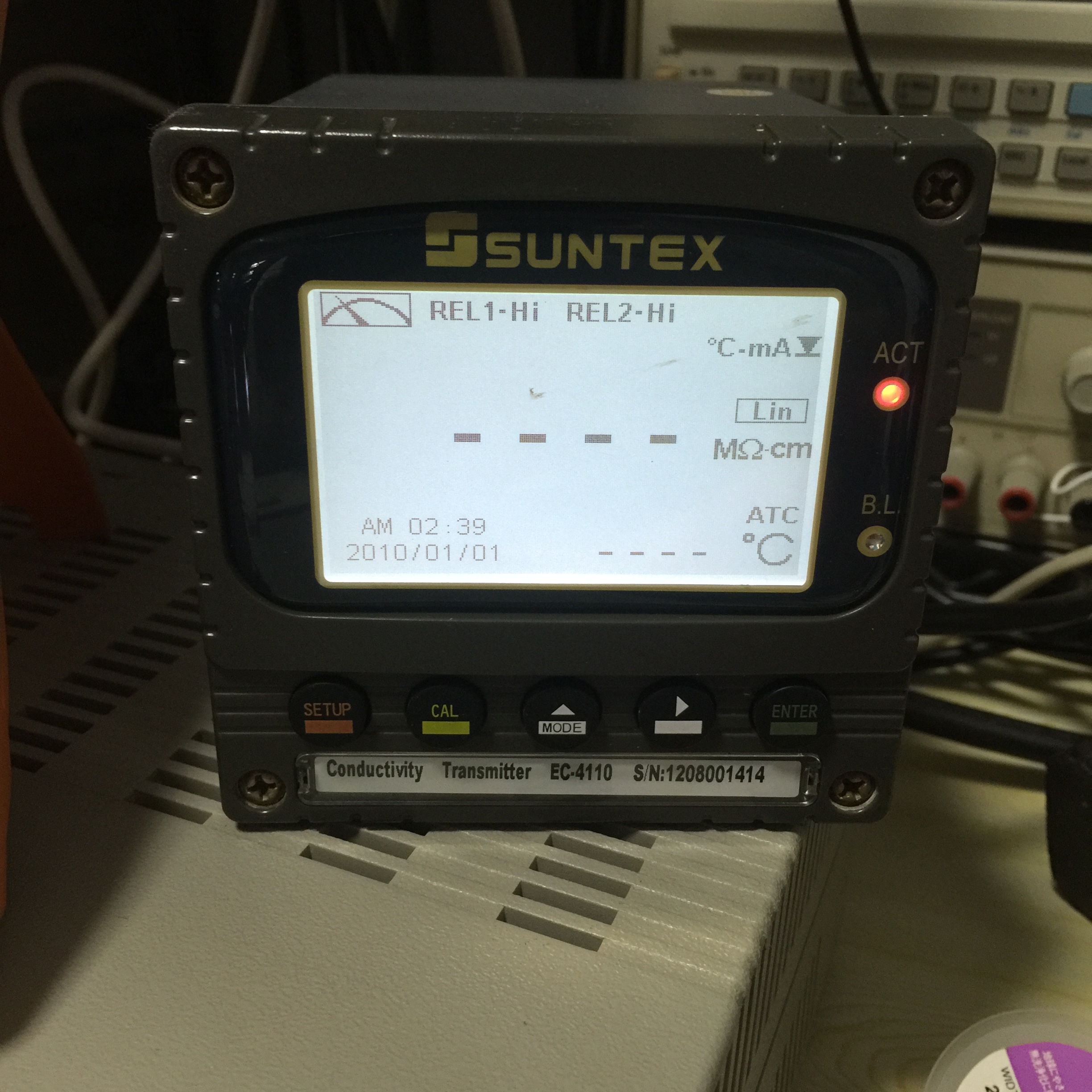
The is a meter used in DI water conductivity monitoring and failure symptom is no display. Quick analysis show that the Switch Mode power supply inside has no output. Thus it should be an easy fix but …
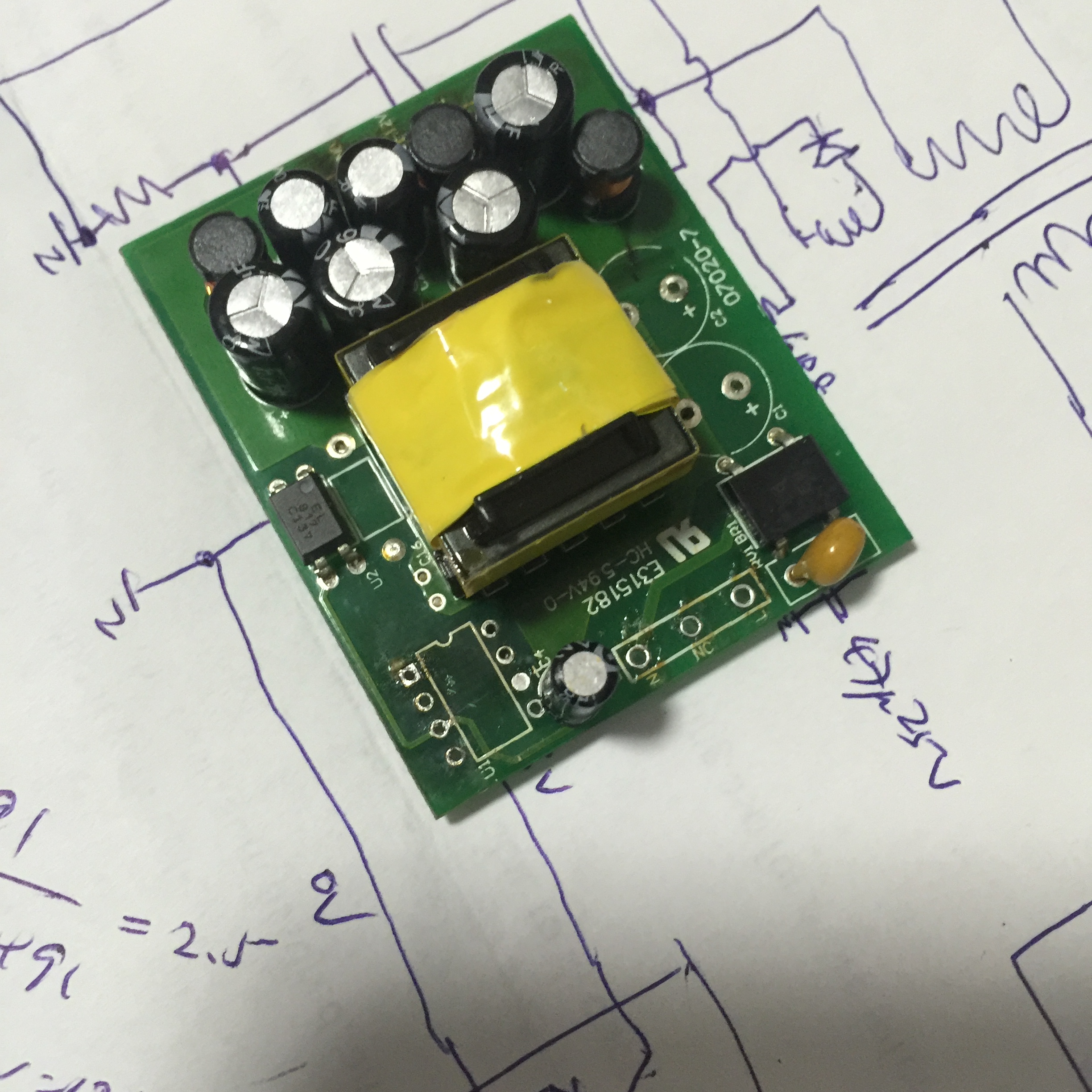
The switch mode power supply provide about 10W to the controller and thus it is stack on top of bigger pcb using some pin header. The AC main filter, fuse, current limit etc are house on the bottom bigger pcb and the whole SWPS is on the small PCB. The design is using a DIP-7 pin IC as the switch but the part number of it is masked (removed). Thus the circuit need to be traced by reverse engineering as shown on the draft. After searching on internet, the only match part is from ROHM BM2Pxx4 series IC. Thus I decided to get in the BM2P014 for trial. Other problem seen in the power supplier PCB is one 10u 400V capacitor swell on top and after removing it found capacitor value 99% gone. Thus I also order two Nichicon 105 degC grade for replacement. When I first replace the IC BM2P014, the supplier seems to output voltage but about 2 minutes, there is no more output and thus the NEW IC is spoil! So left only one ICs on hand a bit worry not to get it repaired! After looking around, I remove the capacitor at pin 5 (Vcc supplier filter) and also found no capacitance value! Thus I concluded that the failure is caused by poor filter of the Vcc supply and then kill the ICs after some time. Due to that I also change all the E-cap on the output side of the supply and measurement show that most of the capacitors are out of spec with lower capacitor value due to prolong use of the meter (non stop). I just wonder why the meter use such low grade unbranded so call 105 degC capacitors inside this industry meter! The cost to get replacement for this meter is about US$650 !!!
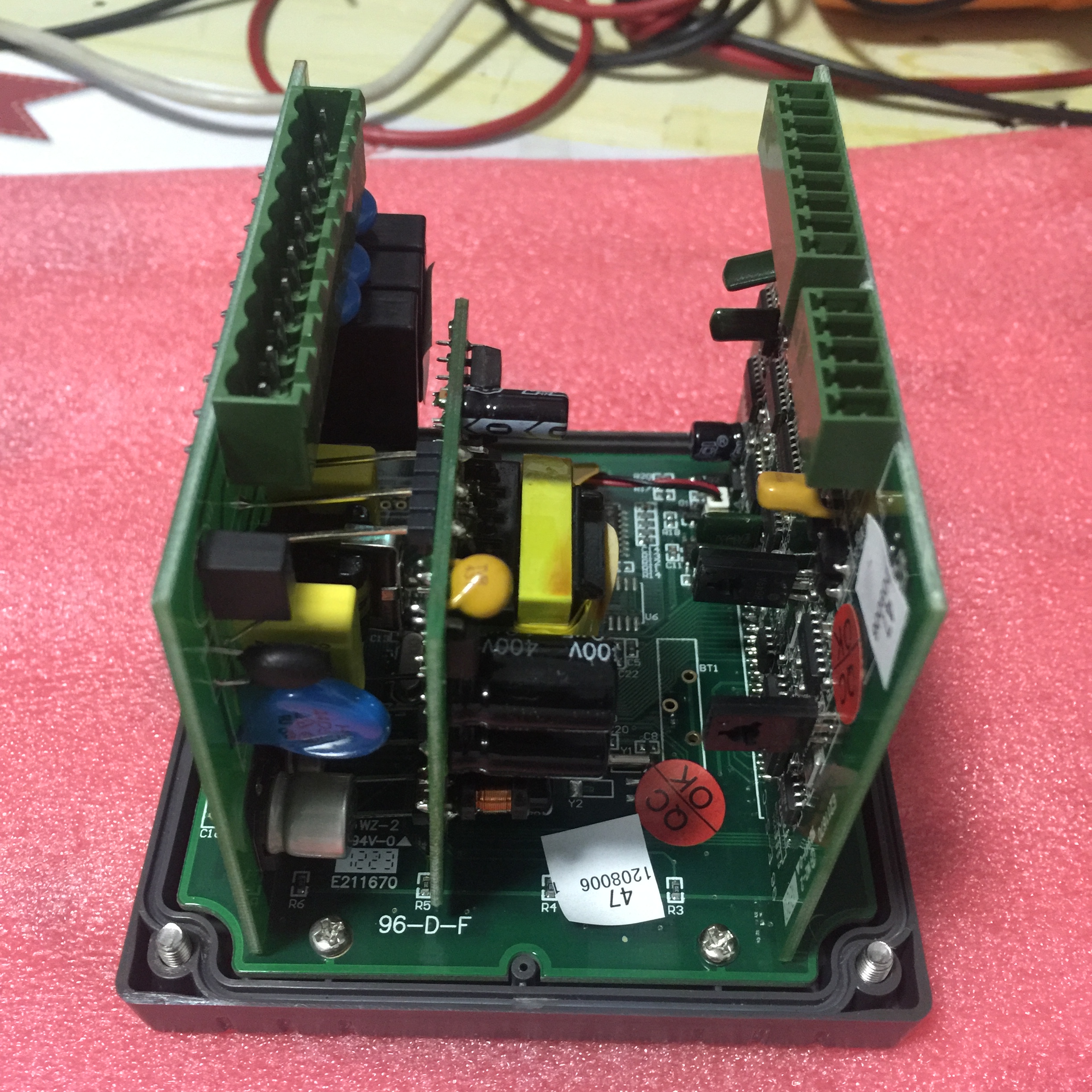
PCB Assembly:
 SMPS with DIP-7 IC and two 10u 400V capacitors removed:
Draft circuit of the SMPS: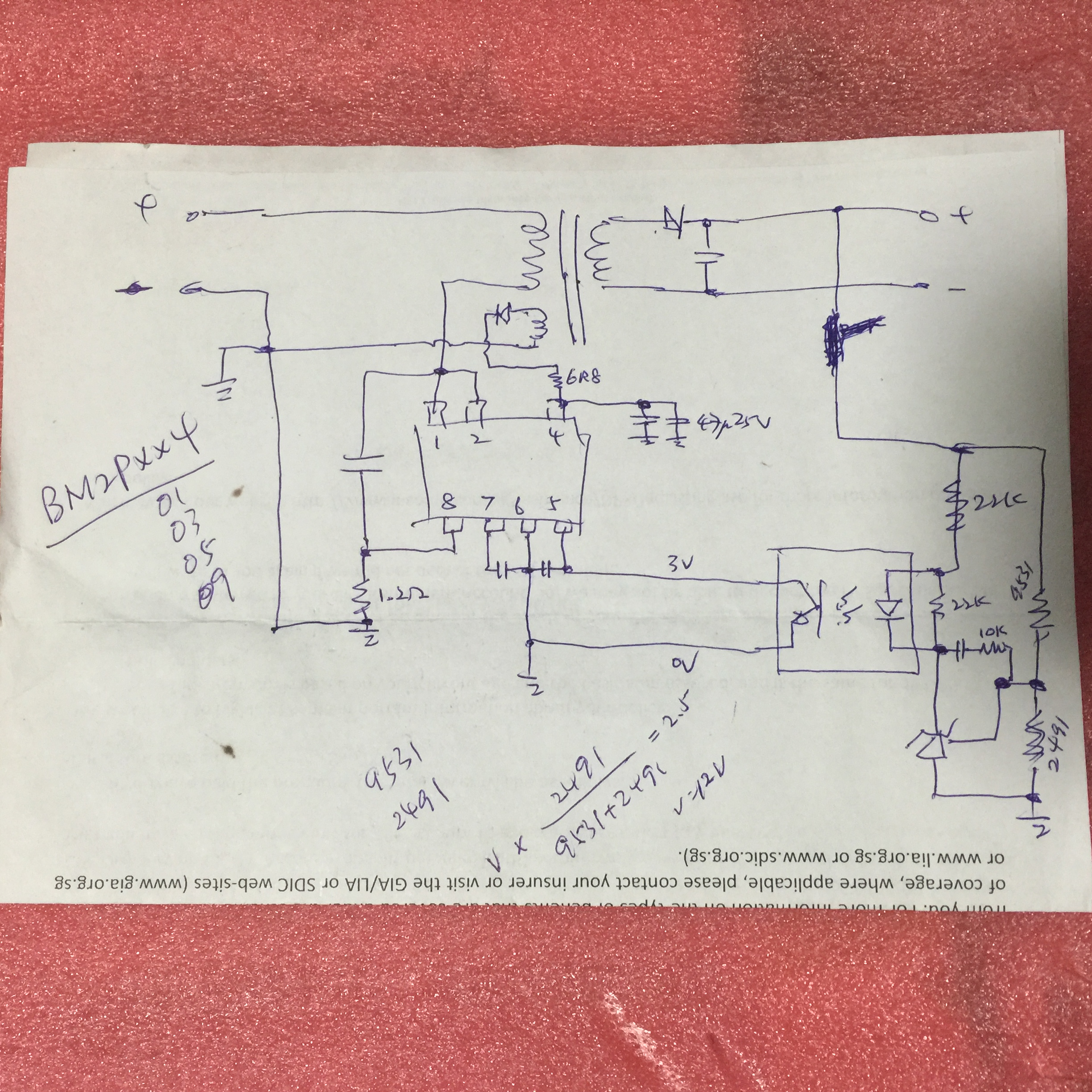
Components ordered from Mouser: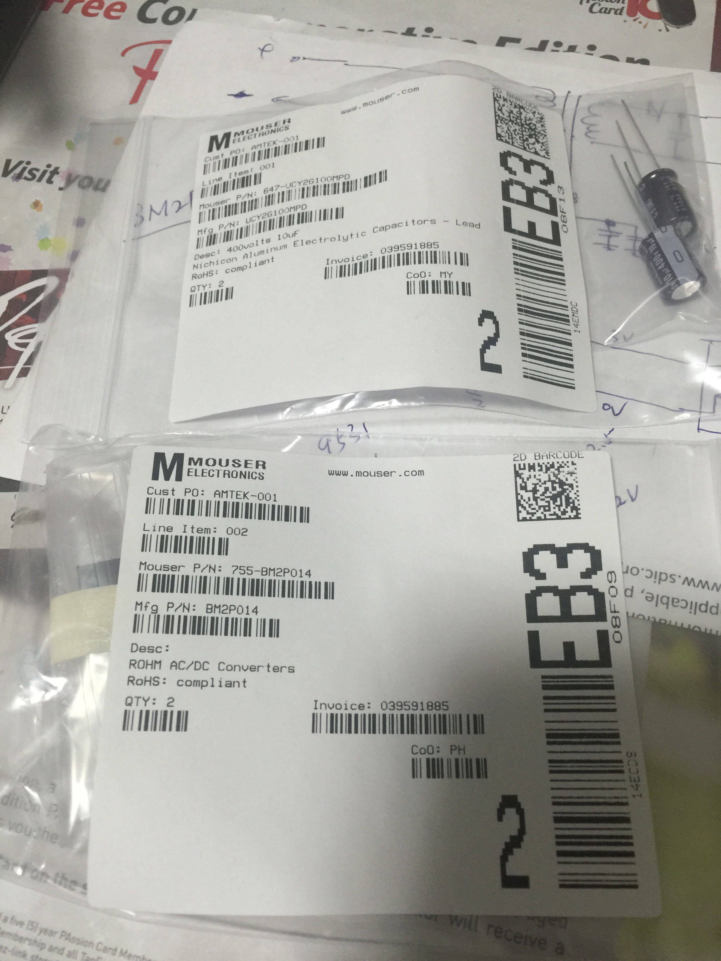
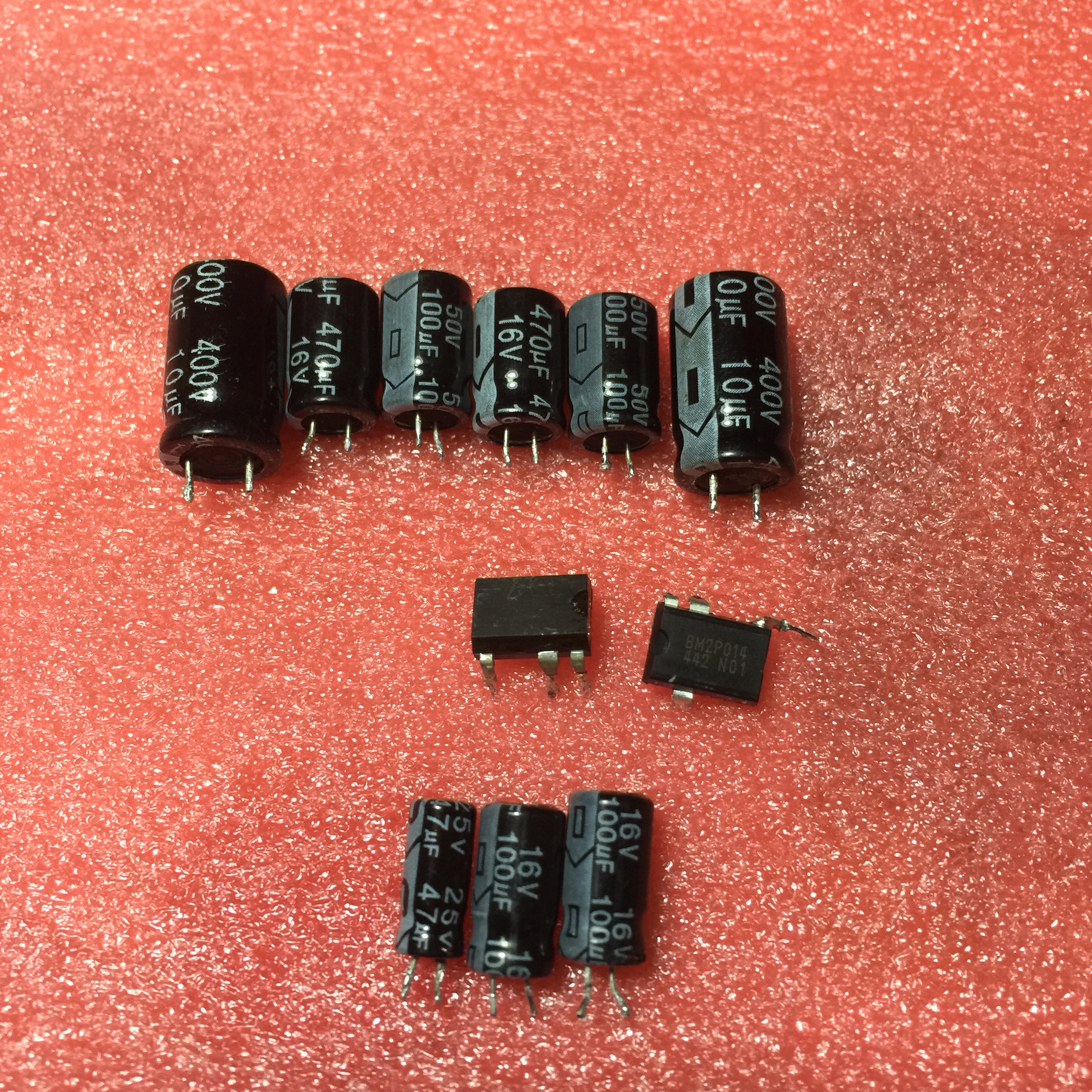
Defective parts from SMPS:
Final repaired power supply: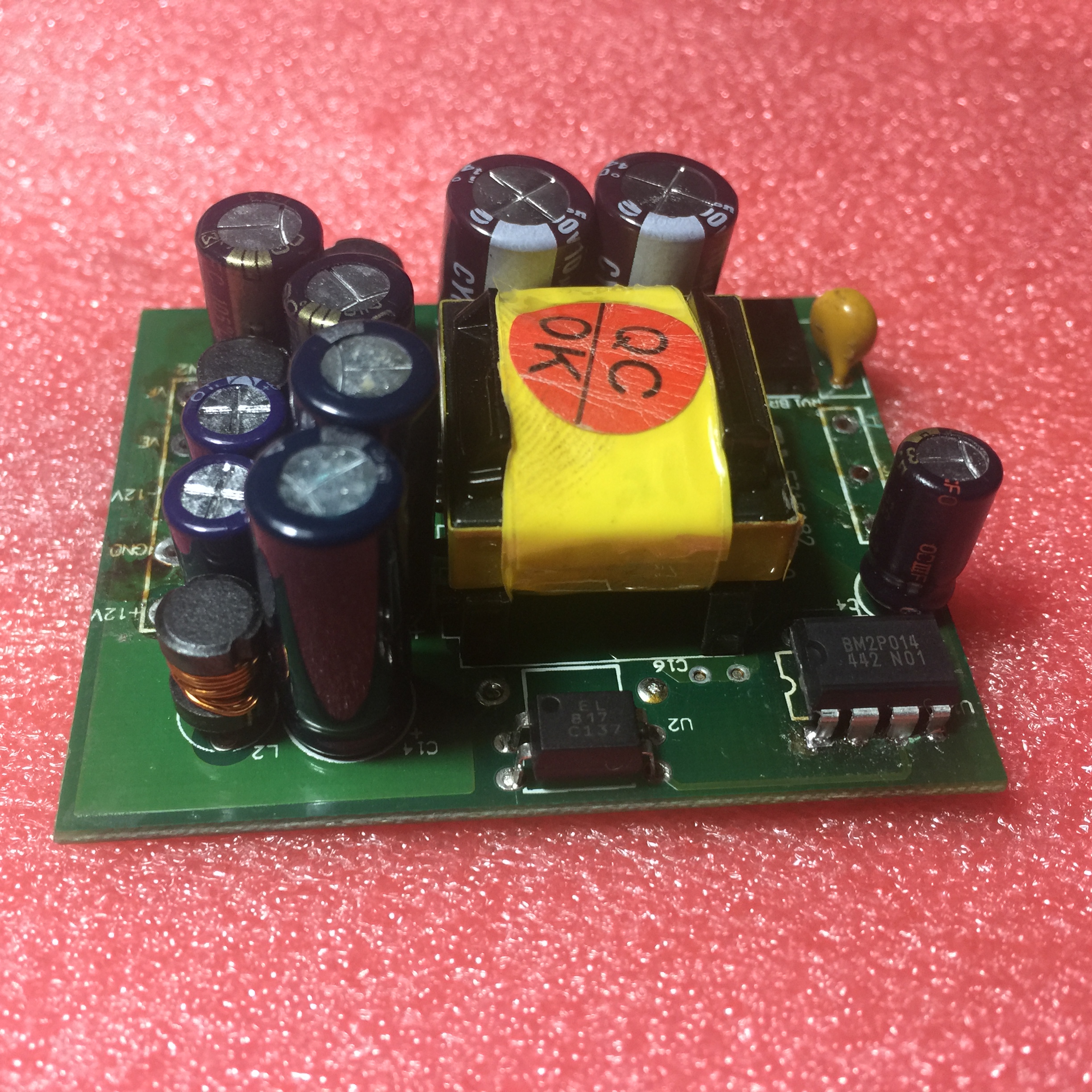
Note the output of power supply is +12V 0V -12V; Ve is oV and Vf is 24V.
END.