FET Audio | Hi-End Audio & Electronics DIY Electronics & Repair

October 29, 2009

D1V3 & D1V33 upgrade to 24bit input mode

Filed under: DAC — Spencer @ 3:02 pm

I remember there is one diyer of D1V3 told me that D1 is not able to receive true 24 bit digital data format.  The reason is that D1 has choosen to use 18 bit modes for CS8414 and SM5842.  In order for D1V3 and D1V33 to receive 24 bit data, I have tried out successfully to use the 24 bit Right Justified mode for both DIR9001 and SM5842.  Below is the details.

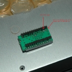
For DIR9001, set Pin 25 FMT0=H and Pin 26 FMT1=L means 24 bit Right Justified output data mode.  This is a easy setting by J1 short and J2 open on the DIR9001 converter board.

For SM5842,  the pin 5 IW1N and Pin 10 IW2N  has to be both Low (GND) for 24 bit data input mode right justified.  In the design of the pcb, there is no jumper setting for SM5842 IW2N (pin 10) which is always tie to +5V (High).  Thus the follow procedure has to be done to make the change to 24bit data input mode.

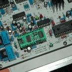
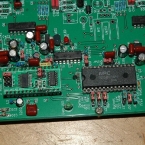
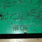
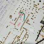
  1. Cut the trace on the bottom of the pcb on both sides of the pin 10 trace as shown.  Cut two line with 1mm width and remove copper in between as in the picture.  Check with ohmmeter for open circuit.
  2. Solder a wire from the Pin 10 of SM5842 to Pin 8 which is ground pin (thin blue wire).
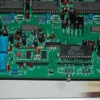
  3. Connect a wire (thick green wire) from +5V supply of SM5842 to the jumper side as show in the pictures.  This is to ensure the jumpers has the +5V supply as usual.
  4. On component side, set J22 to 8414 (18bit) side, i.e. Pin 5 become Low (Ground).

FFT measurements show that the different between 16 and 20 bit signal noise floor is more than 12 db at -80dbFS input for PCM63 DAC.  This proved that the digital data input 24bit right justified mode is working!

For PCM1704, the lowest noise floor is about -132dbV with 24 bit -90dbFS data input.

FFT DAC D1V33 16 vs 20 bit PCM63

FFT DAC D1V33 16 vs 20 bit -80dbFS PCM63

DAC D1V33 63 vs 1704 at FS 24bit

FFT DAC D1V33 1704 at -90dbFS 24bit

Update Mar 13, 2010:

For PMD100 converter board, cut trace between pin 12 and 13.  Short the pin 13 to pin 14 (ground) – PMD100 set to 16 to 24 bit input mode with Left Justified.

Set jumper of DIR9001 J1 – open and J2 – short; this is to set Left Justified output mode for DIR9001.

*** Do not do below change for PCM63 user ***

If you want to change the PMD100 converter board to 24 bit ouput mode (for PCM1704), you have to set pin 10 from L (ground) to H (5V).  The problem with the converter board is that the top and bottom of pin 10 is shorted to ground plan.  Thus you have to cut both trace on top and bottom but it is impossible to modify if you have soldered the chip or IC socket! 

Short pin 10 to pin 11 if you can isolated the ground connection on pin 10.  Then you have 24 bit output mode.
Related Images:

October 27, 2009

PCM1704 to PCM63 Converter BD

Filed under: DAC — Spencer @ 10:43 pm

Since I have a PCM1702 to PCM63 converter board pcb, I have put a PCM1704 on same adaptor board for testing purposes.  The only difference is two supply pins +/-5V need to be reversed.  Thus I do cut trace and add two hard wires at the bottom of the board to fit the supply reverse for PCM1704 DAC chips.

For Capacitor, I use Panasonic FC and also Wima MKS film capacitor for supply decouple as in the pictures.

For PCM1704, the noise floor is a bit lower as you can see from the FFT measurement.

D1V33 FFT with PCM1704

D1V33 FFT with PCM63 lin

Related Images:

October 20, 2009

All Jfet Buffer Balance Line Amp

Filed under: Other Amplifiers — Spencer @ 10:21 am

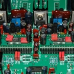
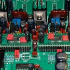
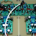
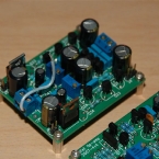
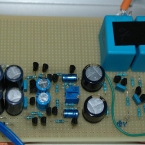
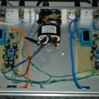
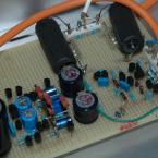
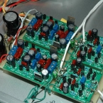
This is also Borbely Erno Design Jfet Buffer and I use this to make my pre-amp.  I use two low noise regulator and 4 buffer module to become a full balance pre-amp.  The sound is very good and distortion is also very low.  I have tried to use a transistor second stage but the sound become aggressive and harsh.  Thus all Jfet is my choice!

Jfet buffer Circuit

Jfet regulator Circuit *updated on Dec 23, 2009*

Jfet Buffer PCB Errors *updated on Jan 15, 2010*

FFT jfet buffer xlr log at 2V

FFT jfet buffer xlr log at 10V

Update on Oct 20:  After redo a bit on the wiring of power supply and put a NTC from star ground to the casing, the distortion has improved to below 0.0001% at 10Vrms output balance mode.  Distortion is also very low at 0.0026% at 1Vrms output.  The good thing about this pre-amp is that the higher the output level, the lower distortion it will be.

Some FFT measurement after improvement:

FFT jfet buffer xlr at 1V

FFT jfet buffer xlr at 10V

Related Images:

October 19, 2009

All Jfet Line Amp with NO FEEDBACK

Filed under: Other Amplifiers — Spencer @ 7:21 pm

This is a Borbely Erno design SE all jfet line amp in one of his article.  I have been using this as a pre-amp since 2006 with Pass power amplifiers like Aleph 60,  F4 & F5.  The gain of this pre-amp is quite high and thus it can be used to drive F4 to sufficient loudness.

The distortion level is also very low at around 0.003% at 1V and 0.026% at 4V output at balance mode.  I am only using +28V dc due to transformer only at 25V x 2 AC.

This pre-amp sound very smooth due to no global negative feedback!  But you see the distortion will increase quite fast as the output level increase!

Last update: 20th Sept, 2010: This is the pre-amp that I am still using at this moment as I like the sound of NO Feedback!!

Borbely Erno All JFET SE line amp Details Updated Sept 21, 2010

Wiring diagram

Was completed 2006/9/16, update FFT measurement on Oct 19, 2009.

FFT jfet SE Bal 1V

FFT jfet SE Bal 4V

Related Images:

October 16, 2009

All Jfet Buffer SE Line Amp

Filed under: Other Amplifiers — Spencer @ 9:18 pm

This preamp is same as the All Jfet Buffer Line Amp except it is only for Single Ended input and output (RCA input/output sockets).  An old Alps volume ( 100K type A) is used at the input instead of step attenuator.

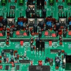
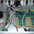
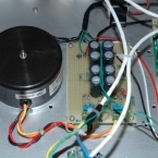
From the picture, you can see there is one single 25V x 2 30VA transformer and two Borbely low noise regulators and two buffer modules are used.  It is very simple but it sound also wonderful when driving a F5.

The FFT measurement show that the hum noise is very small and also distortion is very good at 0.0035% at 1Vrms output level.  At 10Vrms output, the distortion rises to about 0.009%.  Hum and noise is at about 1.2mVrms at maximum volume.

FFT output at 1V, 12k load lin

FFT output at 1V, 12k load log

FFT output at 10V 12k lin

FFT output at 10V 12k log

Related Images:

« Newer PostsOlder Posts »

Powered by WordPress