The equipment also have RIFA cap and thus cleaning and service is needed.
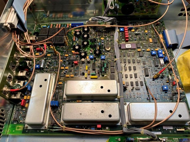
Some inside photos.
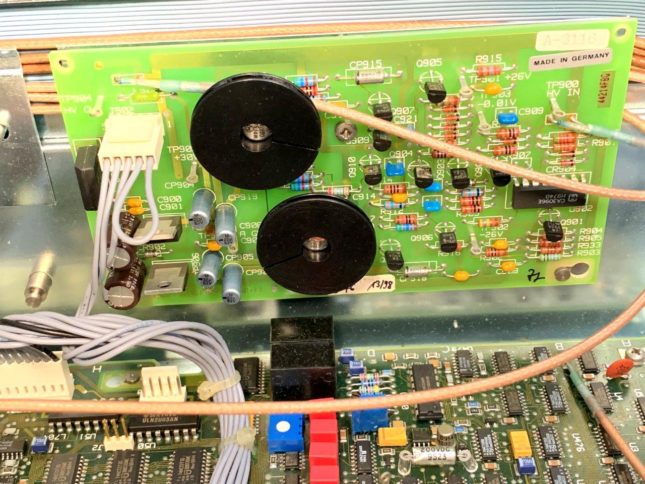
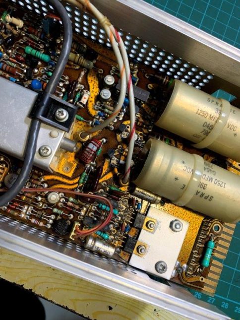
Changed all 3 RIFA capacitors as they have body crack.
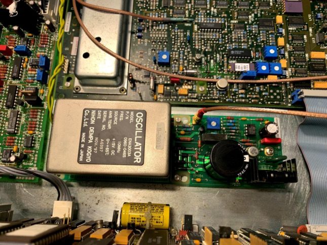
This set come with precision time base 10Mhz clock but the clock do not look very square wave in scope. Jitter is about 30ps, not the best in class.
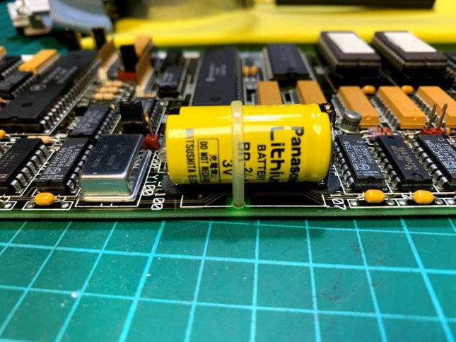
The battery inside still above 3.2V after >25 years.
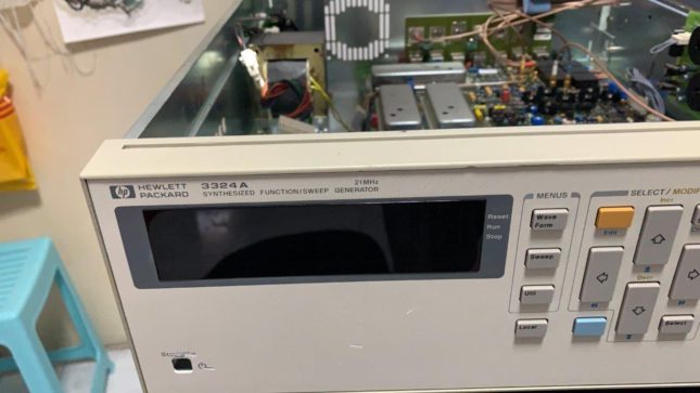
After assembly back, found the output amplitude is not able to set within 1 to 10V, thus there is an issue with the amplifier section which need further trouble shoot! Frequency setting is fine.
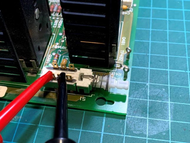
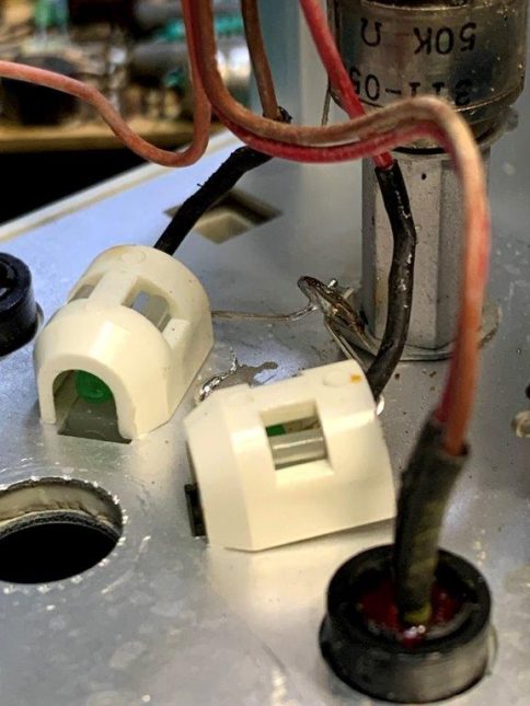
The problem on this sig gen was identified as the power switch one side open circuit at power ON position. Fixing the power switch and the signal gen is back to normal.
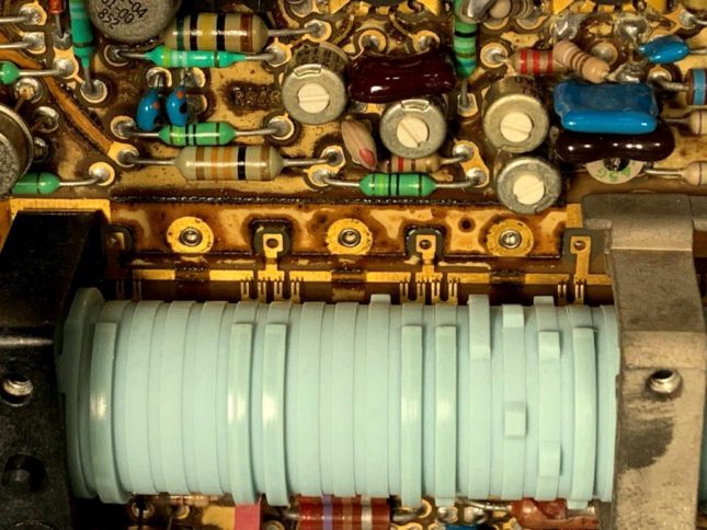
Main board
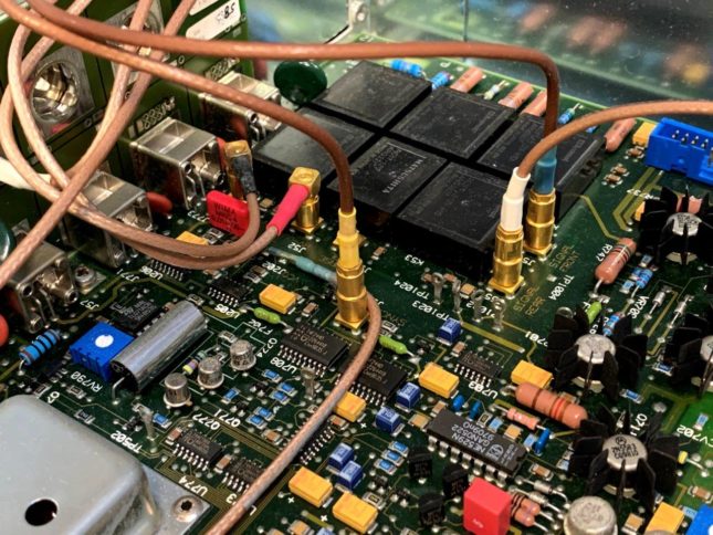
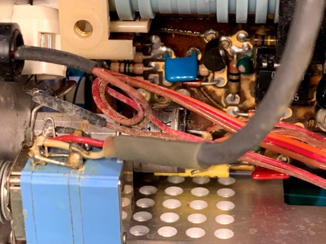
Output section, relays
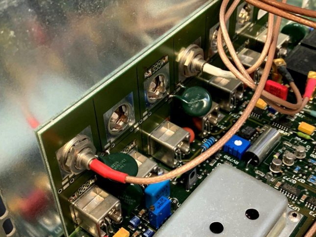
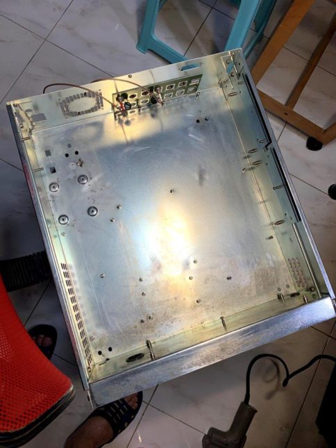
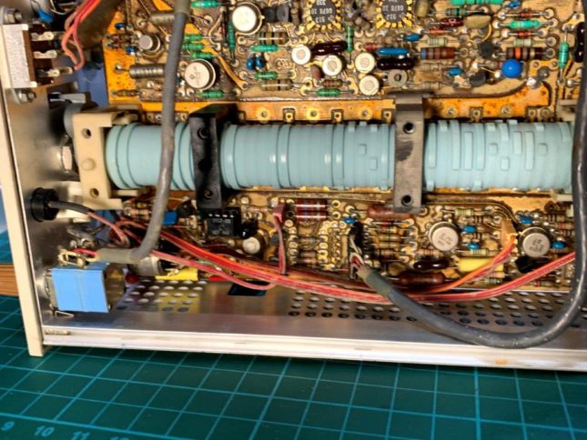
Rear side
High level o/p option
Battery is still above 3V
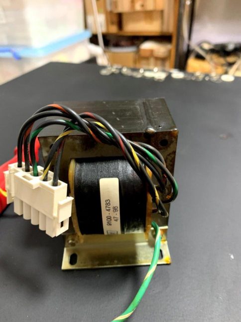
Transformer
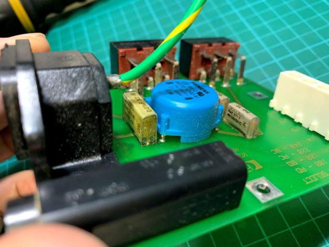
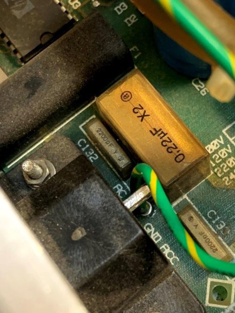
X2 and Y capacitor see crack issues
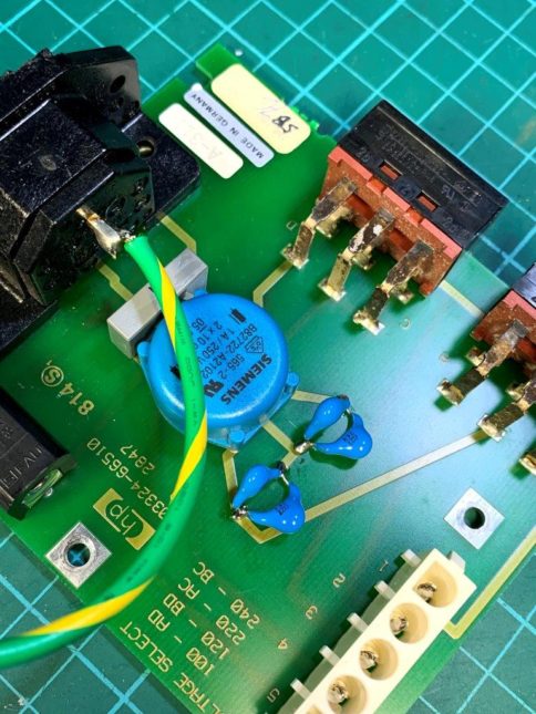
X2 and Y caps replaced
Case is clean with WD-40
10Mhz option
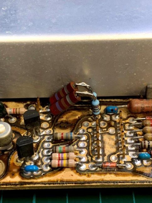
The two connected pins is OPEN when the switch is pressed at ON position.
Related Images:
Comments Off on hp 3324A functional generator service and repair
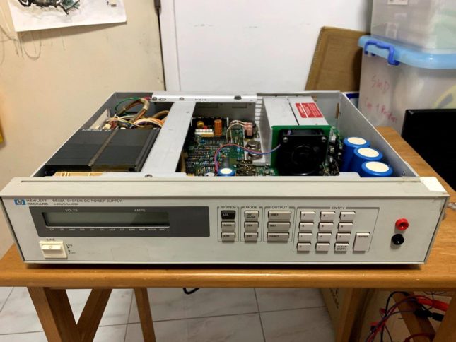
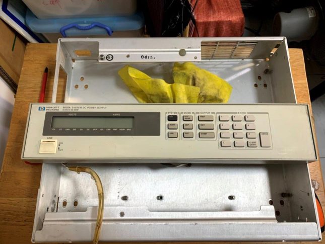
This is a very old hp power supply with HPIB control capability. It is 20V and 5A max. There is a fan to cool the set and thus it is a bit noisy when using this supply. Here is the work done to service it:
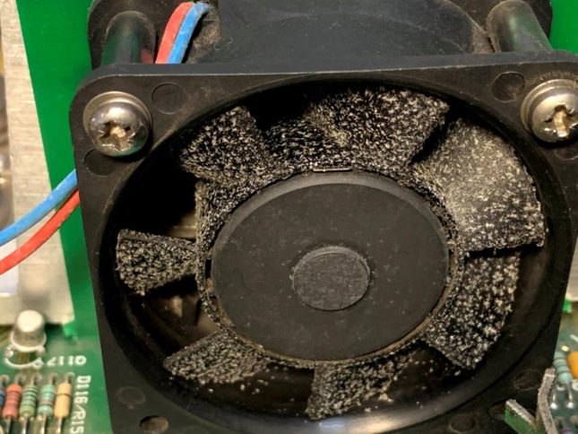
There is lots of dirty stick on the fan and thus cleaning is a must. Also remove the pcb assembly and all item from the case to do 100% cleaning the IPA.
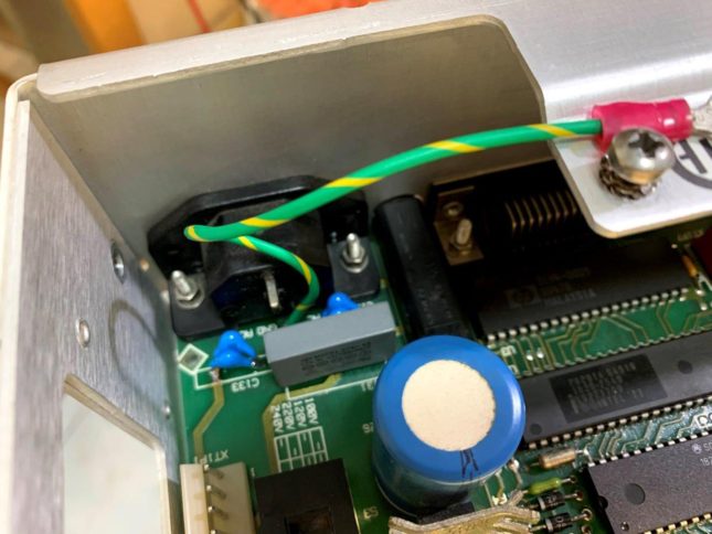
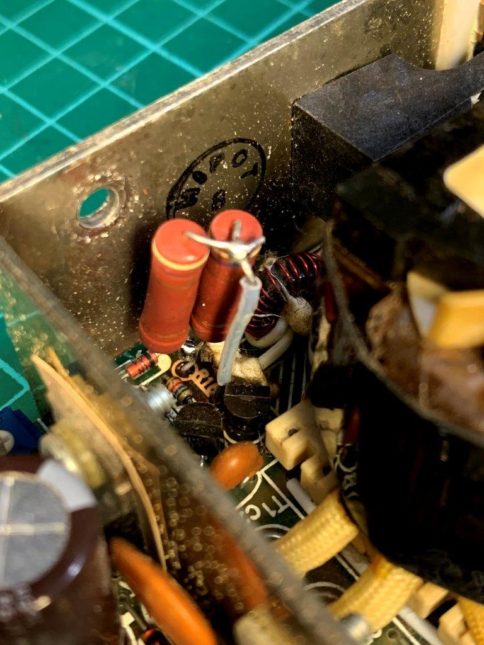
Oh RIFA again and crack on surface, so leaking a bit is the norm!
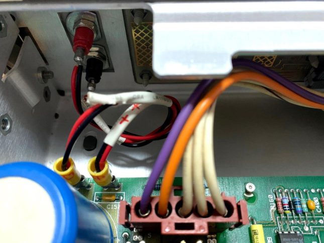
Added front supply connector with sink in type banana socket. Do not want it to extend out as the front panel is also nothing much protruding from the surface.
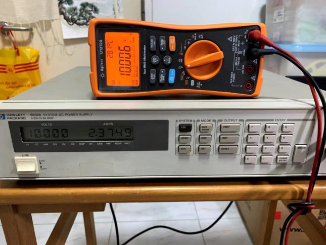
No calibration is required as it is still quite accurate.
Rifa caps crack
Fan sticky with black oily dirt
AC filter caps replaced
Added front output sockets inside photo – washer need to cut on one side to fit the space
Related Images:
Comments Off on hp 6632A service and add front connectors
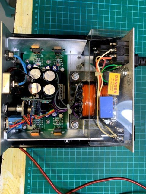
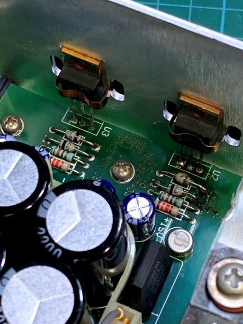
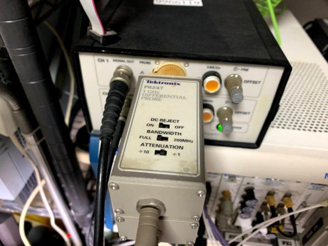
This is a very useful power supply and still selling a good price as Tektronix had made many good probes for use. Example P6247 and ADA400A etc. With this supply, the old probes can be used in modern oscilloscopes. I open up my set and check if there is any RIFA capacitor inside to cause trouble. Luckily there is non as the supplier use a EI transformer. The regulator ICs are just normal type LM317 and LM337 TO-220 type. I see my set was replaced one of them with lots of flux near the diodes! E-cap looks good shape and brand, no need any replacement!
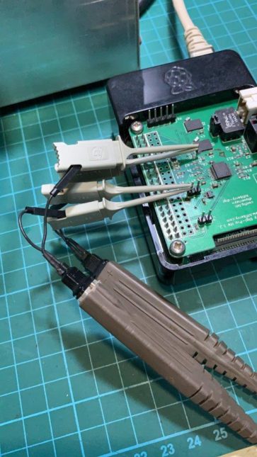
P6247 1GHz probe which is good for measuring jitter on any circuit with differential input mode.
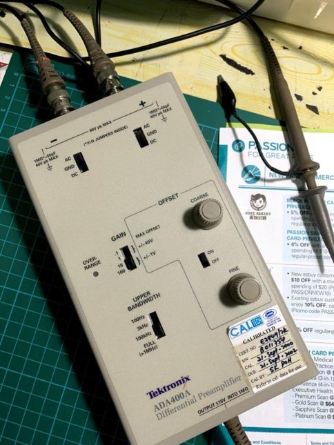
ADA400A is very good for very low level signal even for Biotech usage with extreme high input impedance. It has 0.1, x1, x10 & x100 times and thus 1mV / DIV will become 10uV / DIV in the scope! Also differential design and very good CMRR ratings but limited to 1Mhz bandwidth only. You know what, today Tektronix is still selling this probe!!!
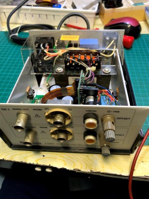
Tek 1103
Tek 1103 top view
One regulator seems replaced before
Tek P6247 tips to measure jitter of Hifi Sperry digi Pro clock jitter
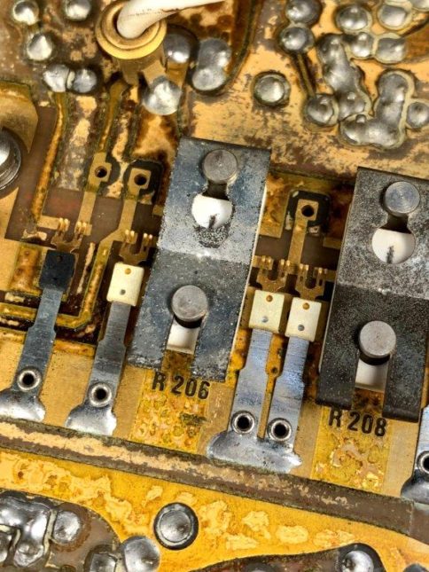
Tek AM503 is the oldest current probe amplifier and there is no LED display on the range. Mine have the PCB corrosion as in the photo. Thus I use Methanol to clean the pcb but after that it is still do not looks very clean! Anyway there are few items need to be restored.
Note that all the old E-capacitors after checking is still working fine, no replacement !
One light bulb is not working, the one always ON! I changed them to LEDs but after that the resistors to limit current need to add in a 1.2k resistors. Note that the light bulb is driven by Negative voltage and thus I need to re-install the polarity of LEDs! I also reverse the two wire position and thus I need to reverse the plug on the pcb to get the right light on the current switch.
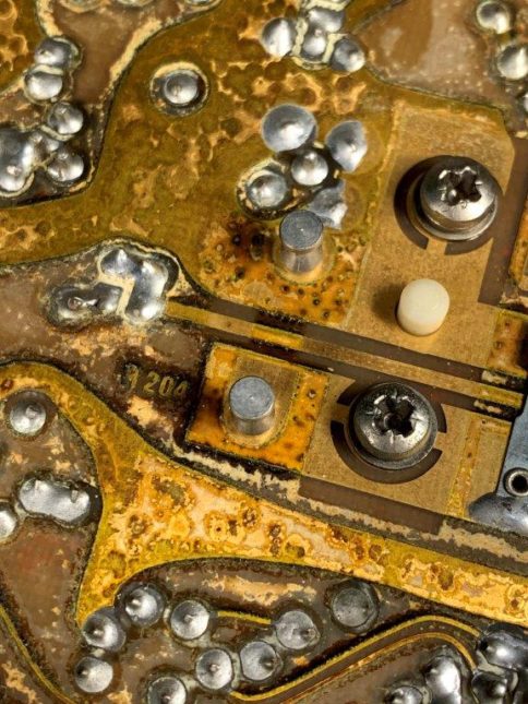
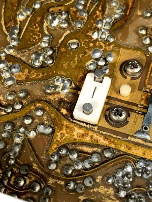
The Rotation current selection switch is a long switch covered. It has gold fingers to press on the gold plated PCBs at many locations for top and bottom side. The contacts are in pairs and either touch top or bottom side. To sort or to go through the attenuator resistors which is seated at bottom side. Since I have wash the pcb, I need to take out all the attenuator resistors to clean them one by one! There is lots of gold on this pcb and resistors or transistors!
The last thing I do not like the design of regulator of this instrument is that there are two power transistors located at the power supply unit bottom chassis for heat sinking. The connection is through the long gold fingers slots which sometimes may give to contact issue and make the power regulator not functioning well. Thus care must be taken when plug in the module into the power supply TM501.
Nothing wrong with the A6302 after disassembly for cleaning. Care must be taken to put back the ground contact springs and do not loss the metal bead. The current transformer is also be handle carefully.
Related Images:
Comments Off on Tektronix AM503 current Probe amplifier & A6302 current probe service and TM501 Power supply.
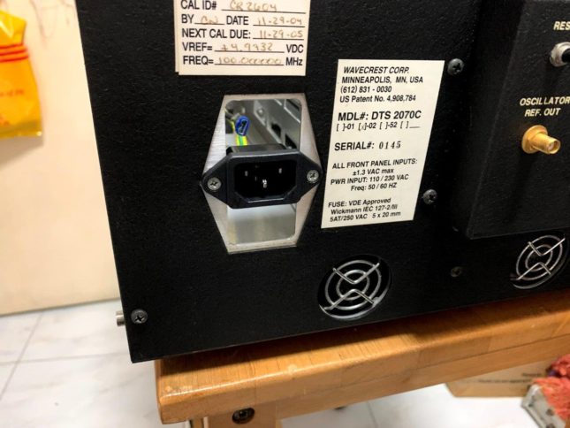
As in Photo, the IEC socket is missing due to burnt about 10 years ago. Since then no repair attempt is done as I am not using that very often. Until recently I have more time at home and now here is the summary of repair done:
It took about two days to repair the set due to two power supply issue. To remove the supply is not easy as the bottom main board must be removed first! There are SMA + 6 screws for main board. Plus there are shield at the input socket connected by 9 screws with shielding plates hiding below the display module!
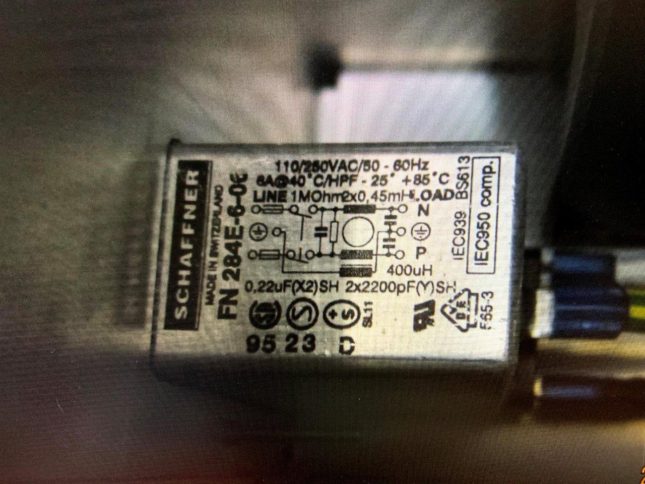
The IEC socket was replace by normal socket without filter for use first. The original FN-284E-06 part cost US$40 per!!! Internal wire is rerouted so that it can reach the IEC socket near the rear panel.
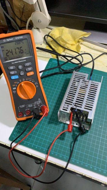
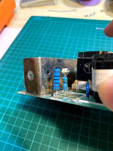
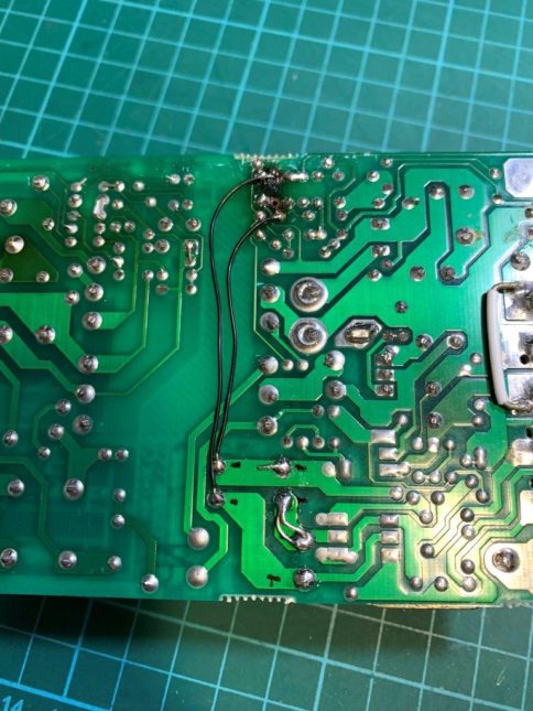
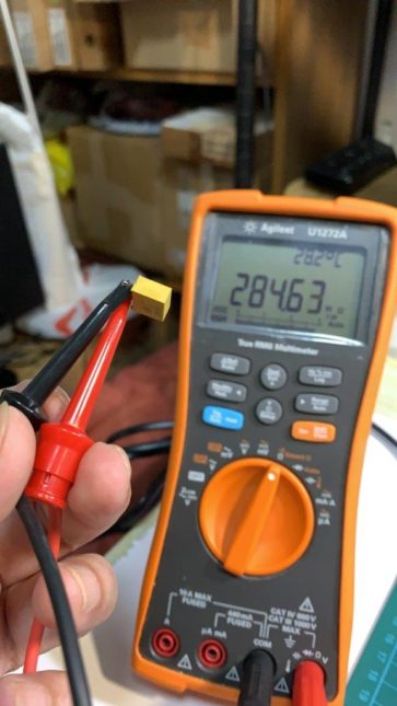
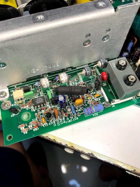
24 V supplier (smaller) is taken out for visual inspection but see a resistor has overheated and make the PCB darken! Blue resistor is remove with (Orange White Brown) 390ohm but actual measured is 90 ohm! Attempt to put two 470 ohm in parallel to same location but pad already peel off ! After repaired the big supply, burnt in for about 3 minutes cause the 24V supply voltage drop and give switching mechanical noise! Second attempt is to relocated the Blue resistor to other side by two wires and use 150 ohm resistors (50 + 100). After that is works fine. Loading test show is can do up to 1.5A with no issue. Also switch up and down time is faster.
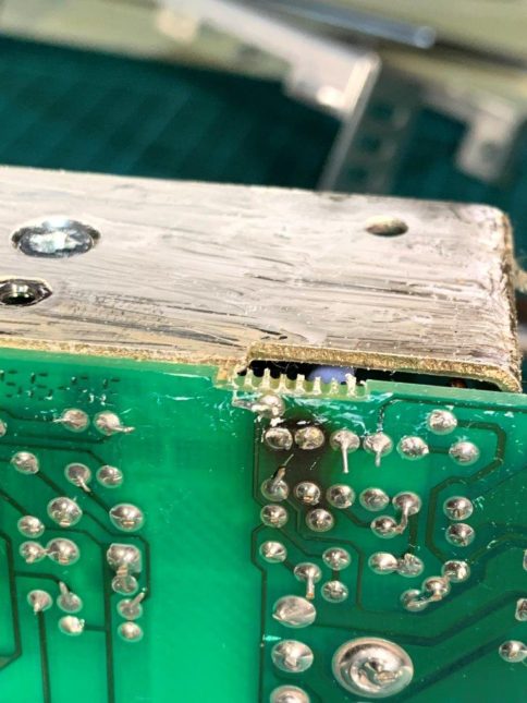
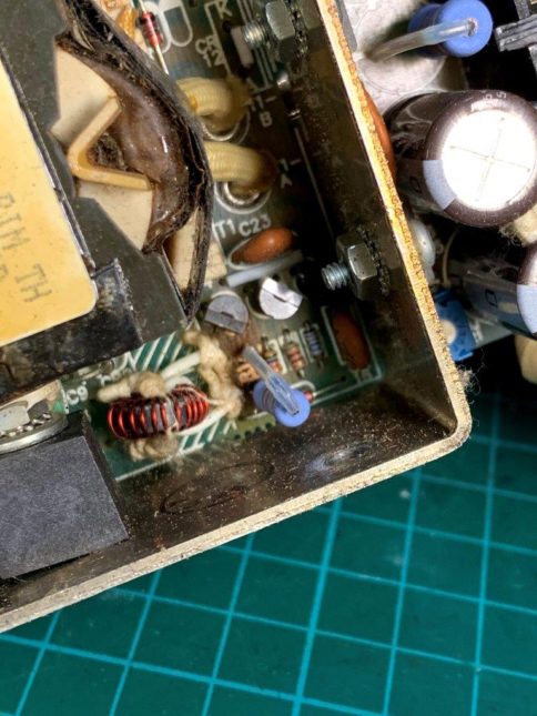
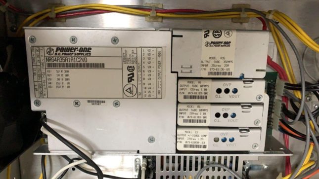
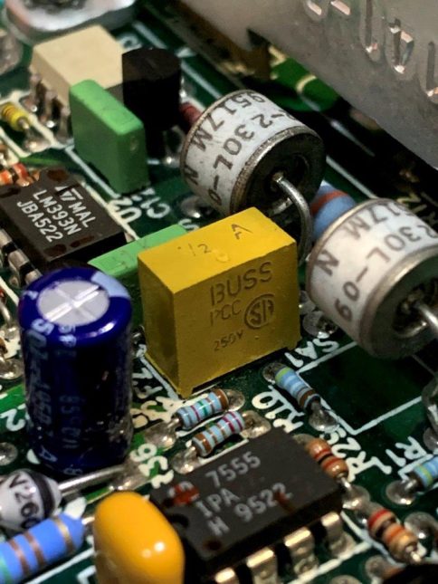
Big supply is total dead with no output for all rails 5V, -5V, -5V, +15V and -15V. Trace the board and found the control ICs are with no power. Initial suspect is the small transformer got issue. Later measure the resistance still show some value. Further trace the supply to small transformer power is ground no return path from + high DC voltage to ground. Finally trace to the YELLOW fuse F2 BUSS PCC part. IN fact the fuse is put in the ground return path which is rated 1/2A fast blow type. To get replacement, the cost is 2.5USD each and take time. I decide to use the leaded type and shrink wrap it for insulation as replacement. I have other fuse but only rated 200mA slow but worry it will fail after some time use.
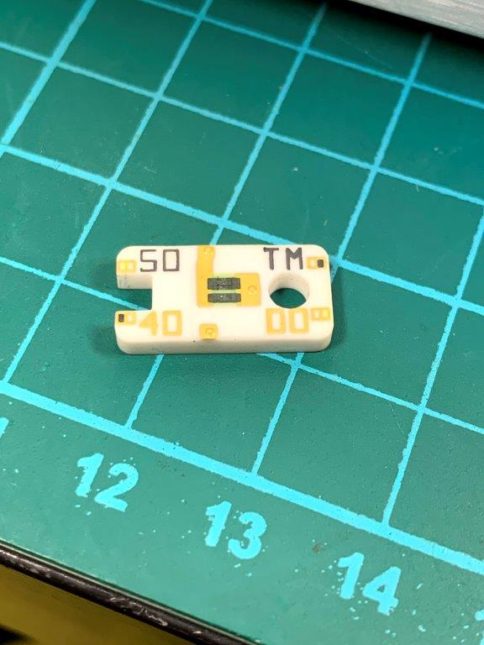
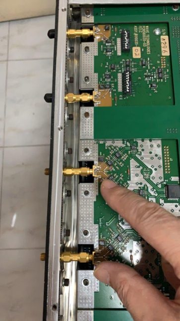
After power Wave set for an hour, do internal CAL and then external CAL. The timing is not able to fully 100% meet spec but very very close or marginal failed only. Anyway it may be due to calibration variations as I do not own the original shorts cap from Wave but use only 50 ohm termination for external calibration.
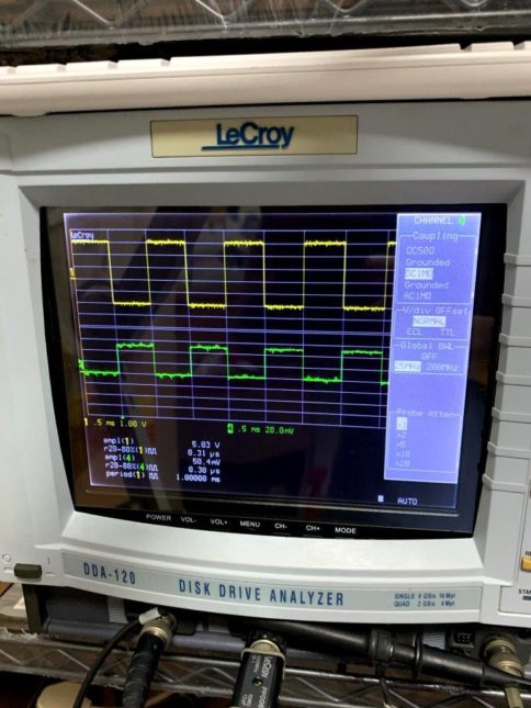
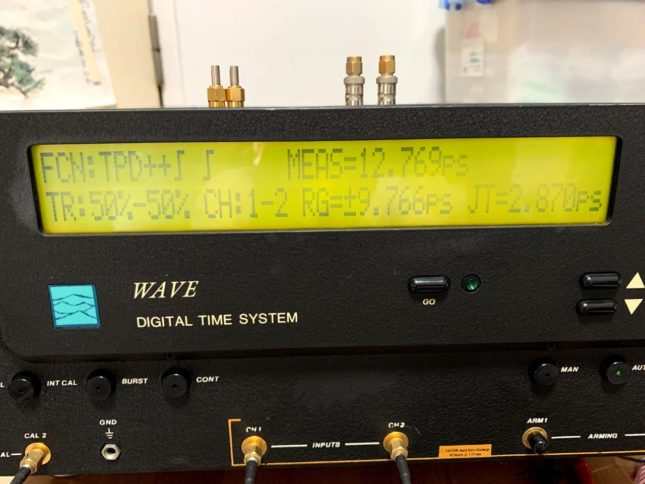
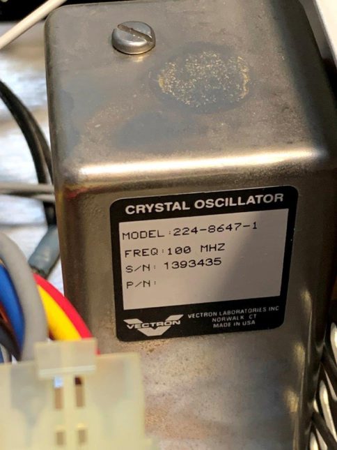
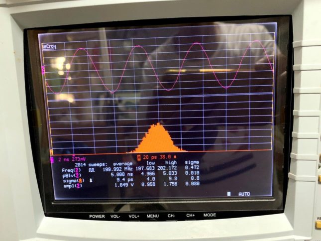
The last picture show the 200MHz cal signal feed to Lecroy scope to get about 10ps jitter. The OCXO in the Wave is make by Vectron and claims to be about 3 ps jitter! It is not far but quite close!