FET Audio | Hi-End Audio & Electronics DIY Electronics & Repair

December 12, 2015

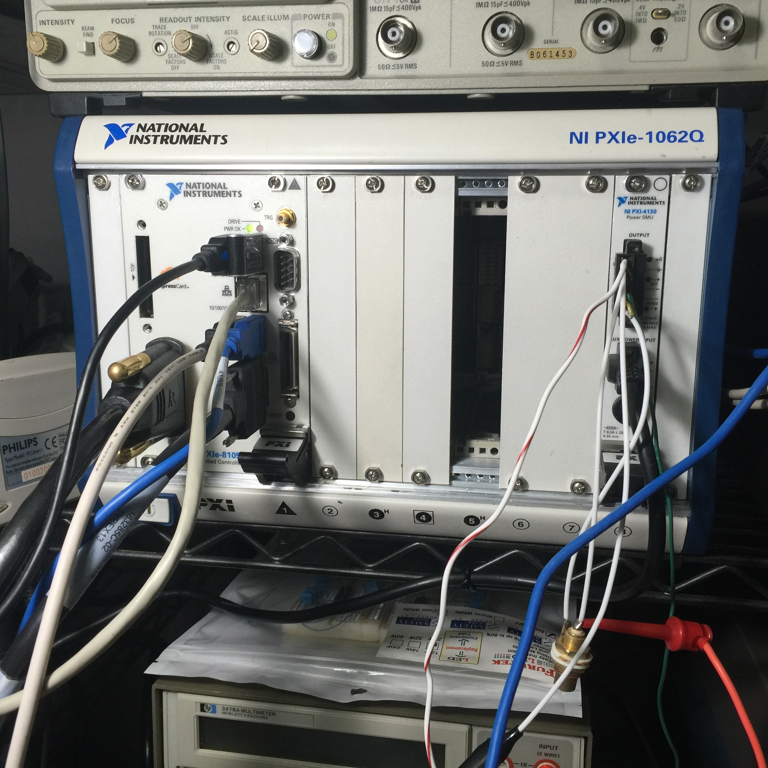
National Instruments PXIe-1062Q, PXIe-8105 & PXI-4130

Filed under: Test Equipment — Spencer @ 10:39 am

These were newly acquired in Nov 2015 from eBay.
IMG_2132

PXIe-1062Q: for both PXI and PXIe cards with power supply.

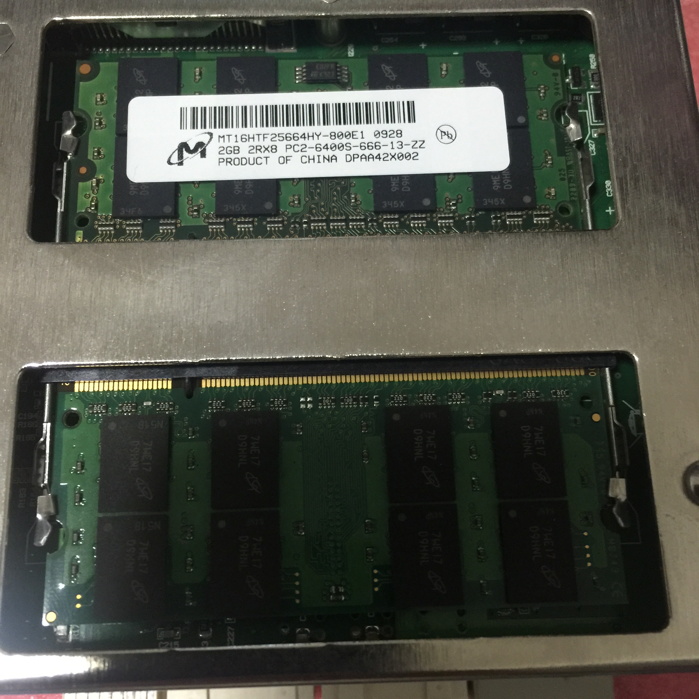
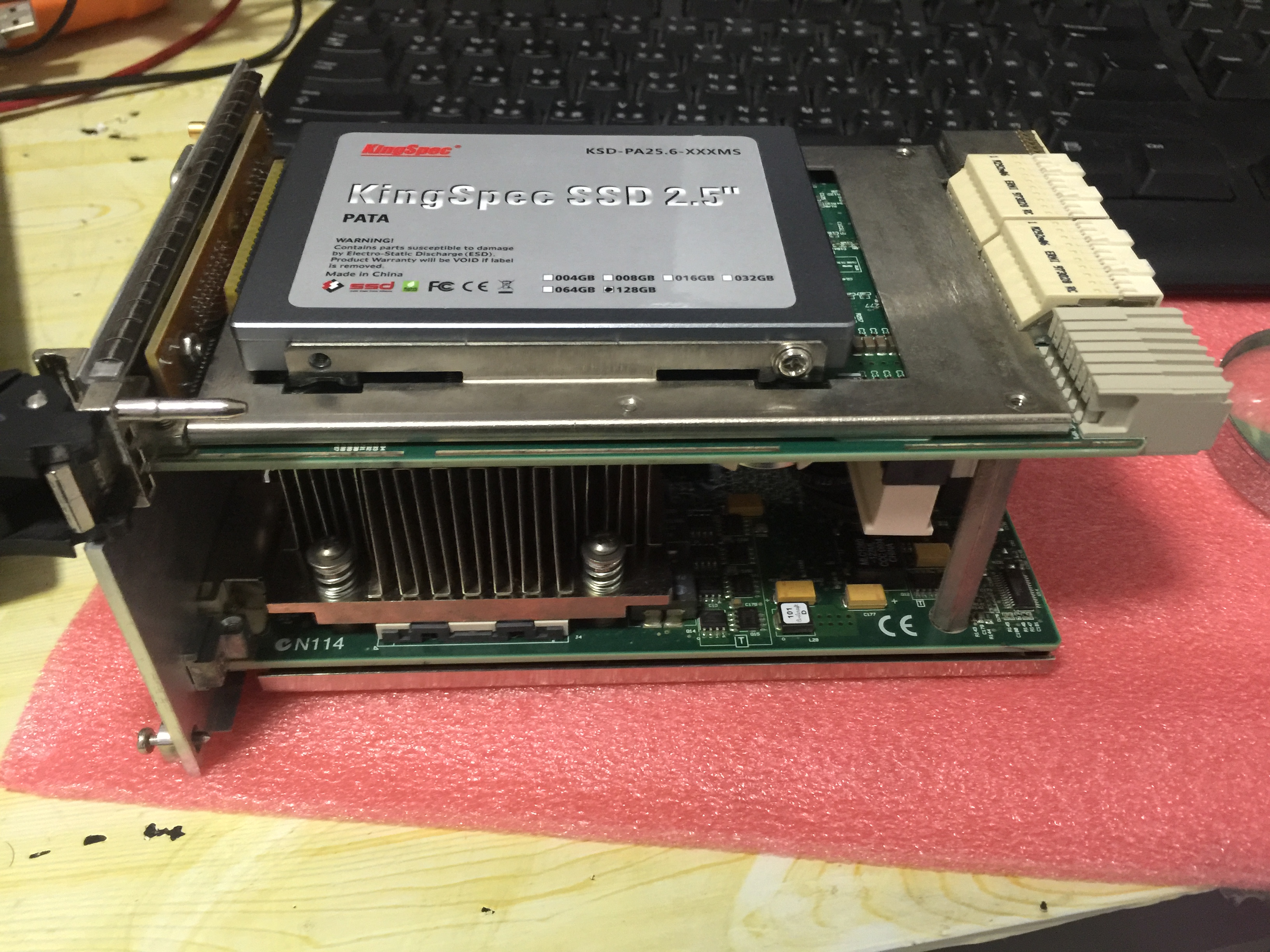
PXIe-8105: controller for the system with upgrade to IDE 120 GB SSD from Kingspec (China) and 4 GB (2 x 2GB) DDR2 RAM.  Actually I found all on hand DDR2 ram with higher speed with work on this controller.  BIOS has also been updated to the latest version 1.3.3.  Speed wise is ok fast now with SSD and 4GB ram under window 7 32bit.
IMG_1662

IMG_2067

PXI-4130: SMU with two output: +/-20V max 2A and 9V 1A.  This supply can be programmed to check transistors or FETs under Labview.

The total cost is about USD$1500 but if getting a SMU with dual output will be much more expensive!

I shall learn and try to develop a program to sort the mosfet 2SK1530 / 2SJ201 soon.  Sorting of the Toshiba 2SK170 / J74 is also very good as the speed is supper fast and reading is stable with no oscillation concern.

USB GPIB adaptor 82357B from Agilent has big issue to link up with other equipment on the NI controller even I follow the steps as what is advised by Aglient website.  Finally I get the original NI GPIB cable Type X13 183285-02 and every things works perfectly.  No wonder the price of second hand USB-GPIB cable from Agilent is half of that from NI!

Changing the 3V back up battery in the PXIe-8105 controller must need reset the reset jumper pins or else the controller cannot boot up at all.

END
Related Images:

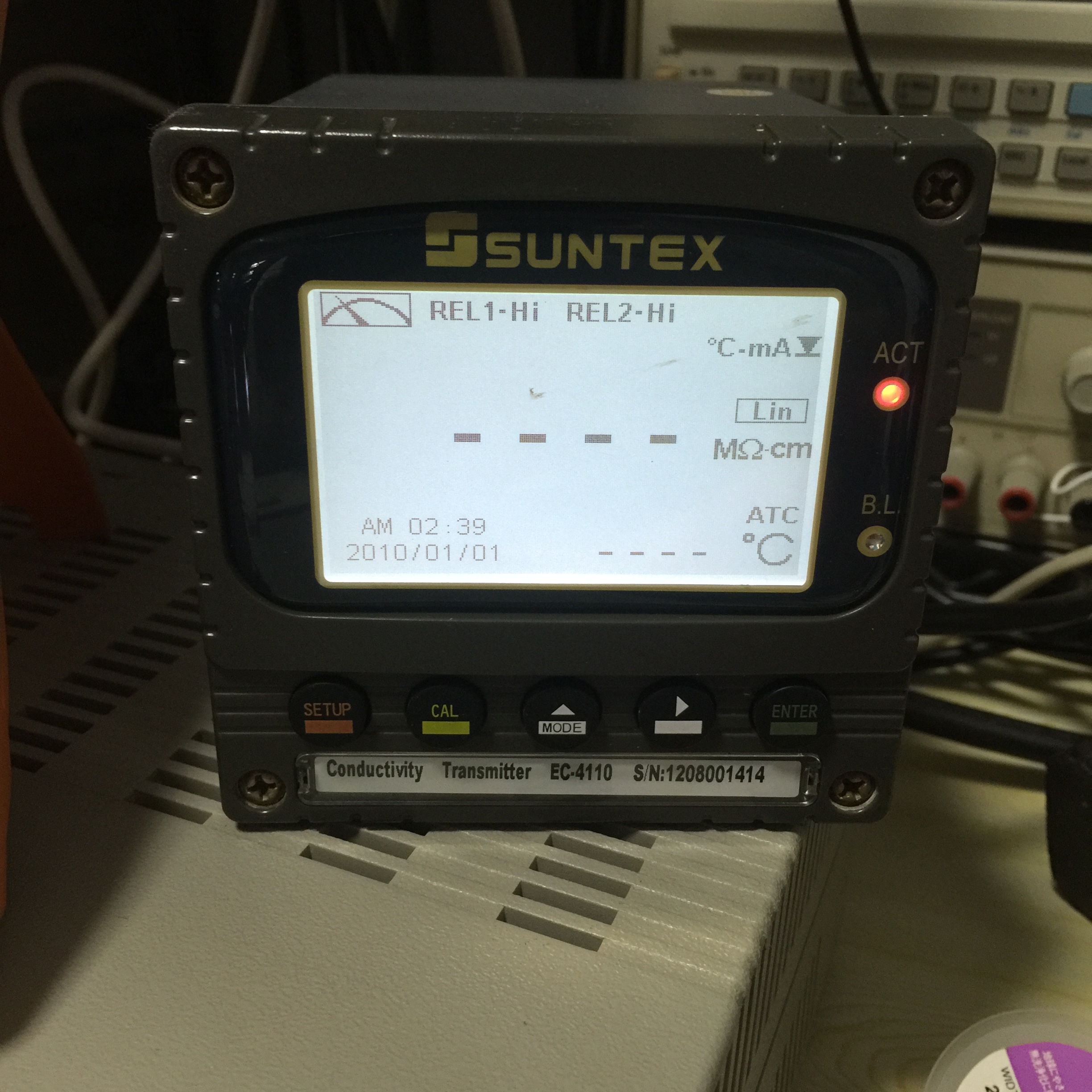
Suntex EC-4110 conductivity transmitter repair

Filed under: Others — Spencer @ 10:01 am

The is a meter used in DI water conductivity monitoring and failure symptom is no display.  Quick analysis show that the Switch Mode power supply inside has no output.  Thus it should be an easy fix but …

IMG_2128

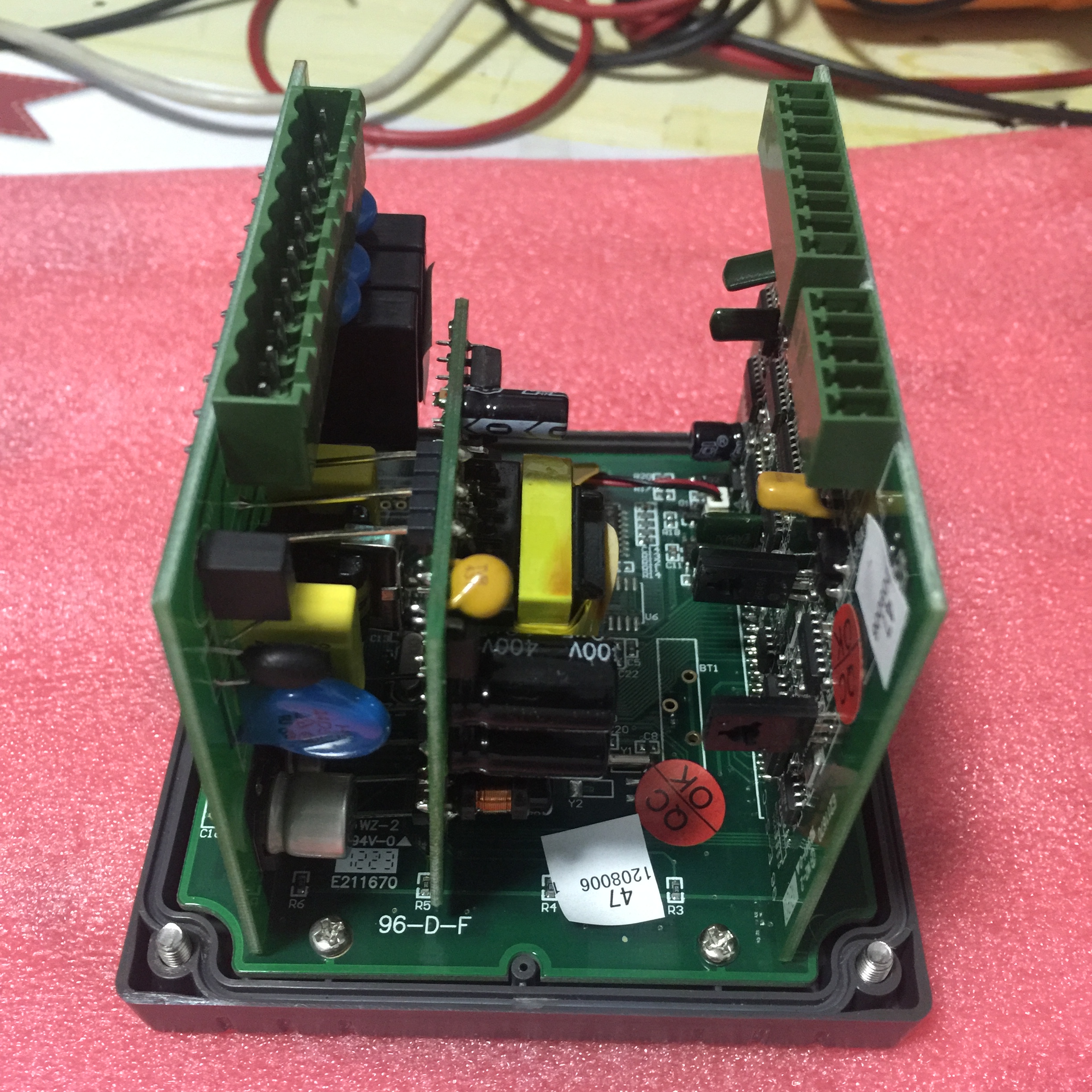
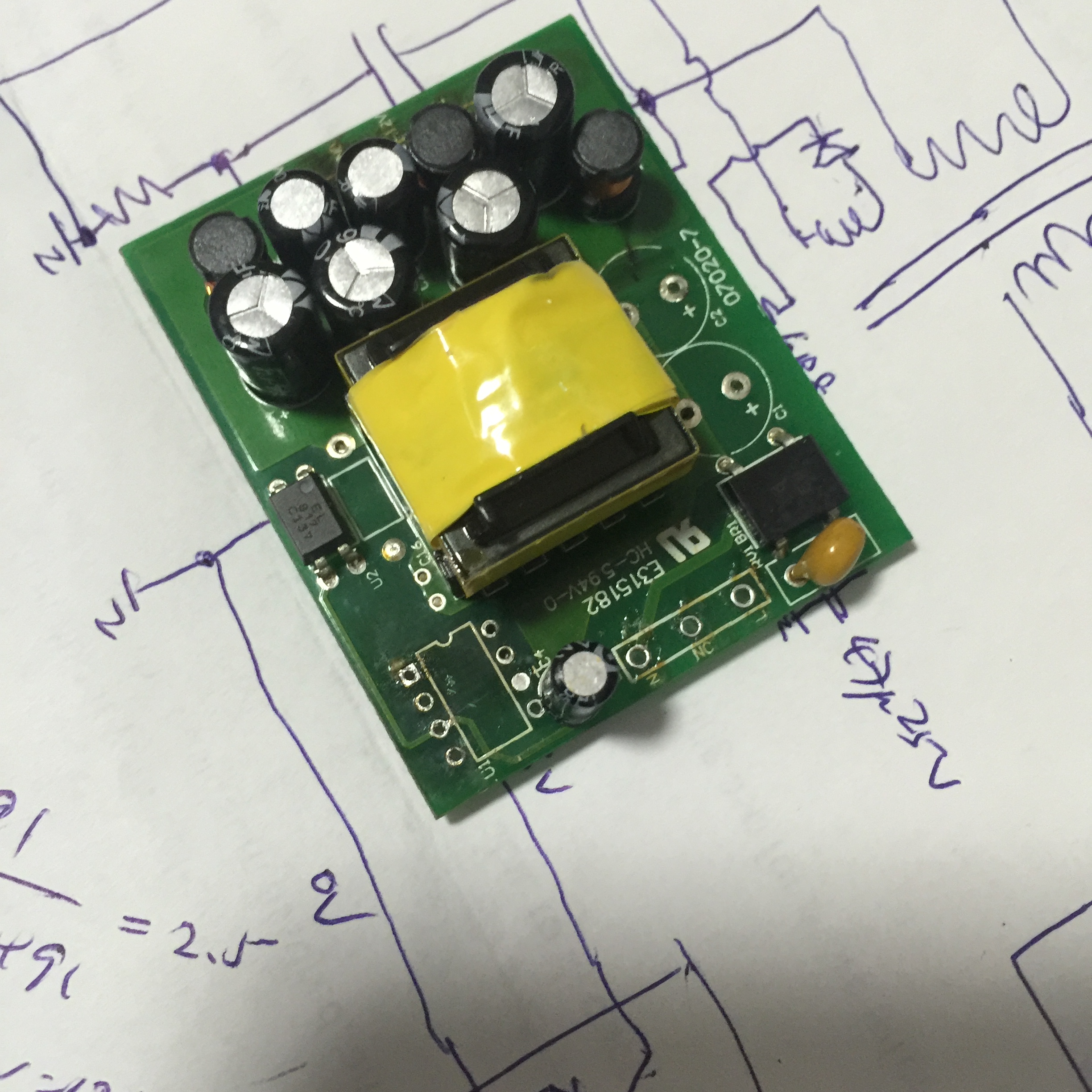
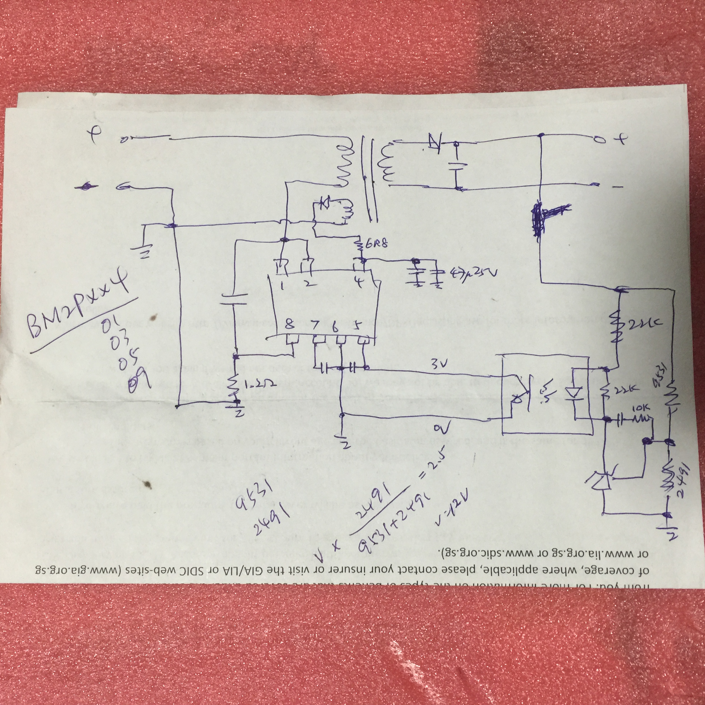
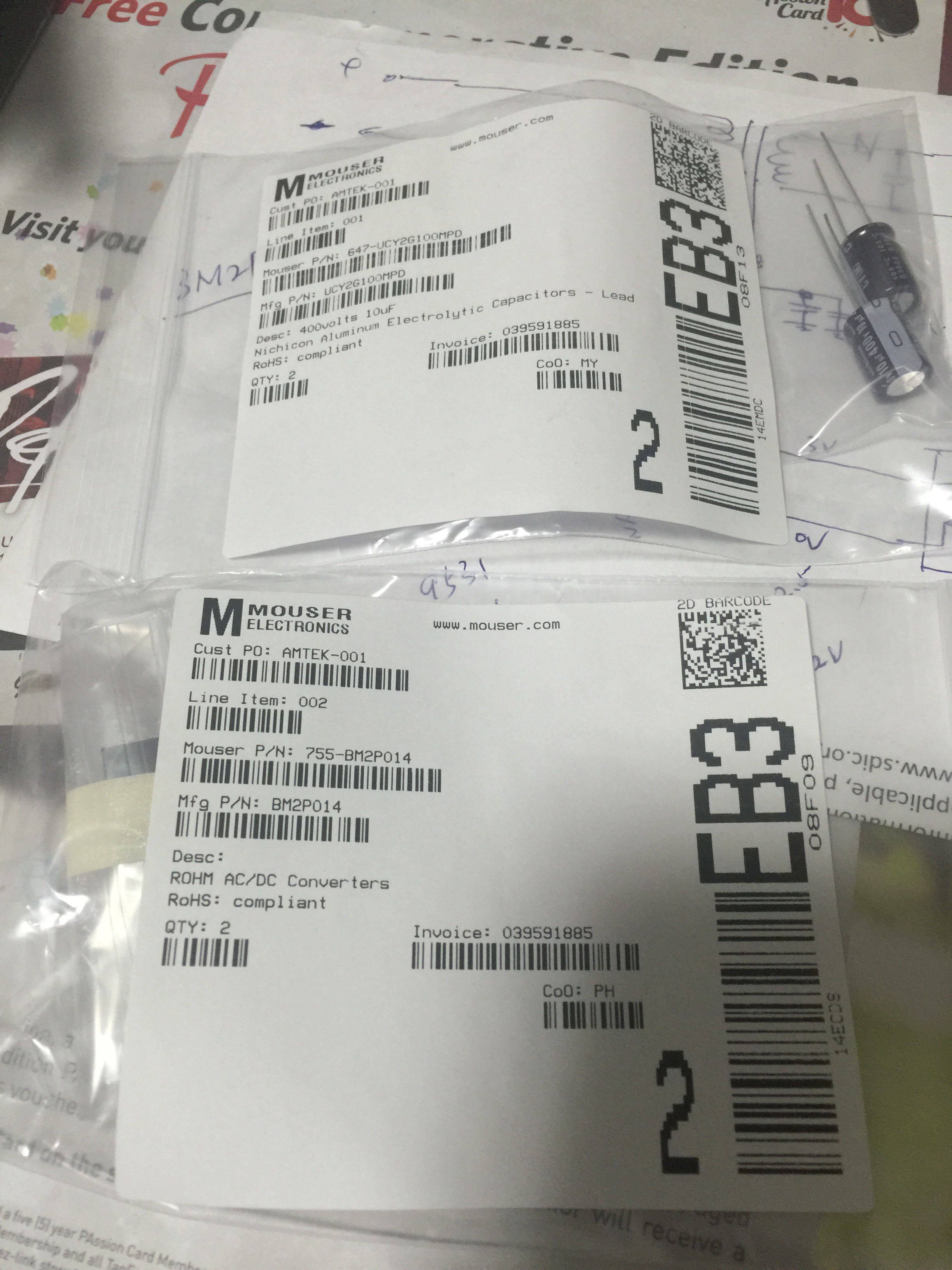
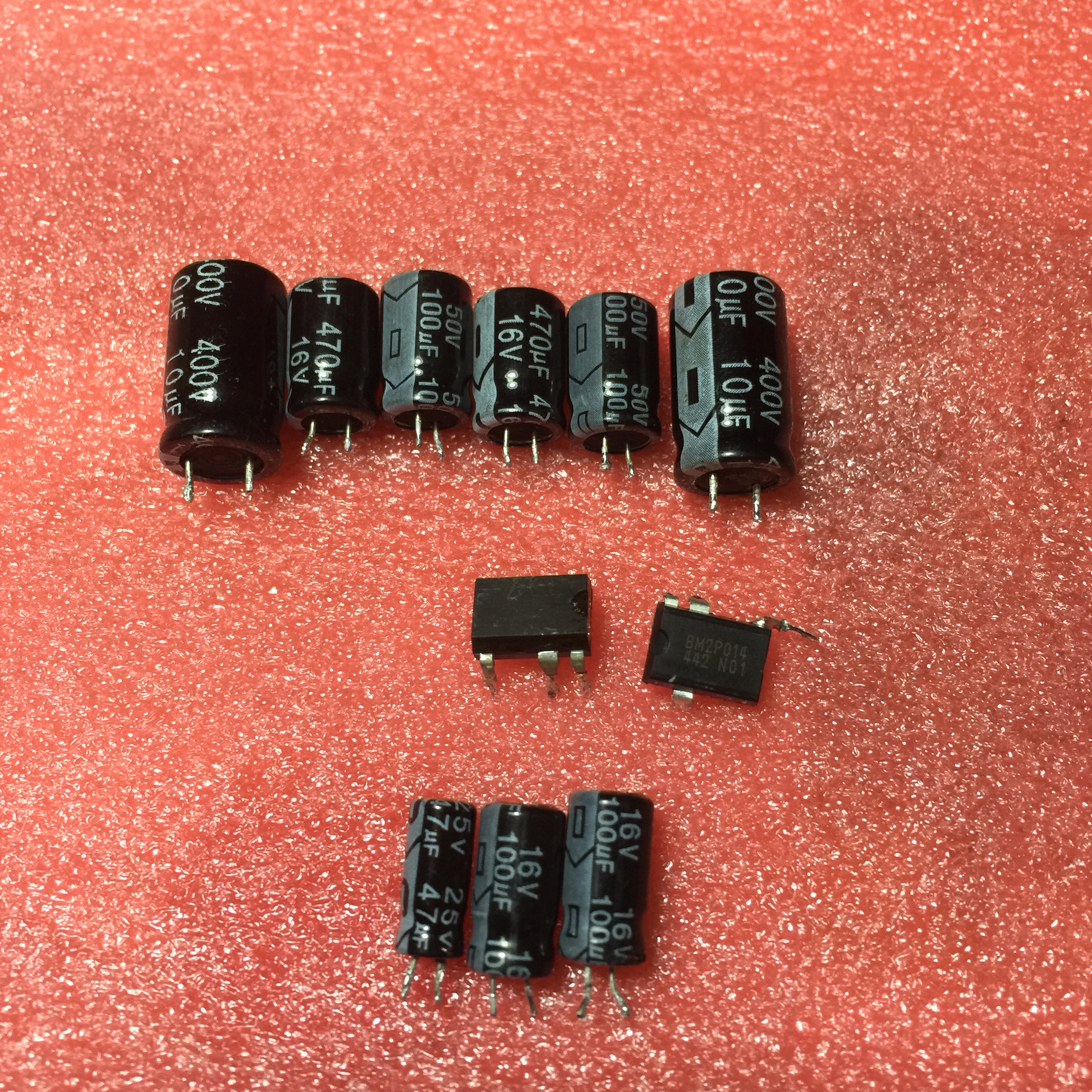
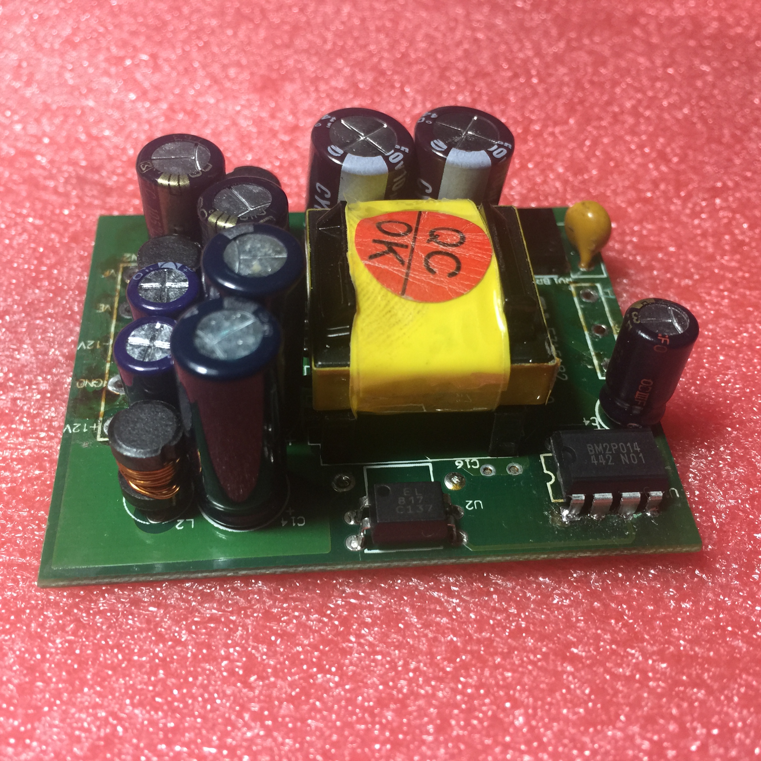
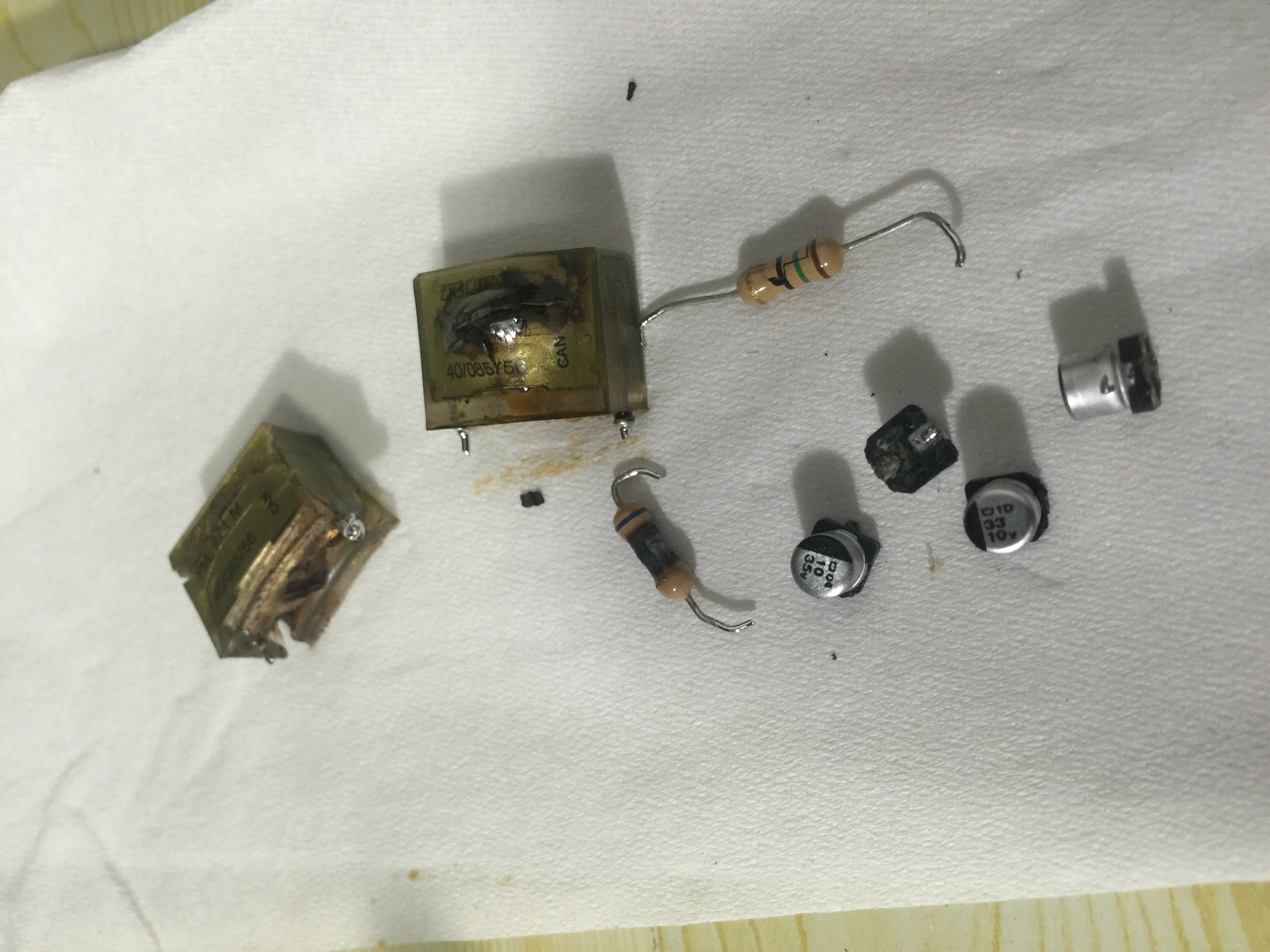
The switch mode power supply provide about 10W to the controller and thus it is stack on top of bigger pcb using some pin header.  The AC main filter, fuse, current limit etc are house on the bottom bigger pcb and the whole SWPS is on the small PCB.  The design is using a DIP-7 pin IC as the switch but the part number of it is masked (removed).  Thus the circuit need to be traced by reverse engineering as shown on the draft.  After searching on internet, the only match part is from ROHM BM2Pxx4 series IC.  Thus I decided to get in the BM2P014 for trial.  Other problem seen in the power supplier PCB is one 10u 400V capacitor swell on top and after removing it found capacitor value 99% gone.  Thus I also order two Nichicon 105 degC grade for replacement.  When I first replace the IC BM2P014, the supplier seems to output voltage but about 2 minutes, there is no more output and thus the NEW IC is spoil!  So left only one ICs on hand a bit worry not to get it repaired!  After looking around, I remove the capacitor at pin 5 (Vcc supplier filter) and also found no capacitance value!  Thus I concluded that the failure is caused by poor filter of the Vcc supply and then kill the ICs after some time.  Due to that I also change all the E-cap on the output side of the supply and measurement show that most of the capacitors are out of spec with lower capacitor value due to prolong use of the meter (non stop).  I just wonder why the meter use such low grade unbranded so call 105 degC capacitors inside this industry meter!  The cost to get replacement for this meter is about US$650 !!!

PCB Assembly:

IMG_2070SMPS with DIP-7 IC and two 10u 400V capacitors removed:

IMG_2084

Draft circuit of the SMPS:IMG_2130

Components ordered from Mouser:IMG_2115

Defective parts from SMPS:

IMG_2126

Final repaired power supply:IMG_2125

Note the output of power supply is +12V 0V -12V; Ve is oV and Vf is 24V.

END.

Related Images:

October 17, 2015

Tektronix 2445B repair step 05 fail 44

Filed under: Test Equipment — Spencer @ 1:53 pm

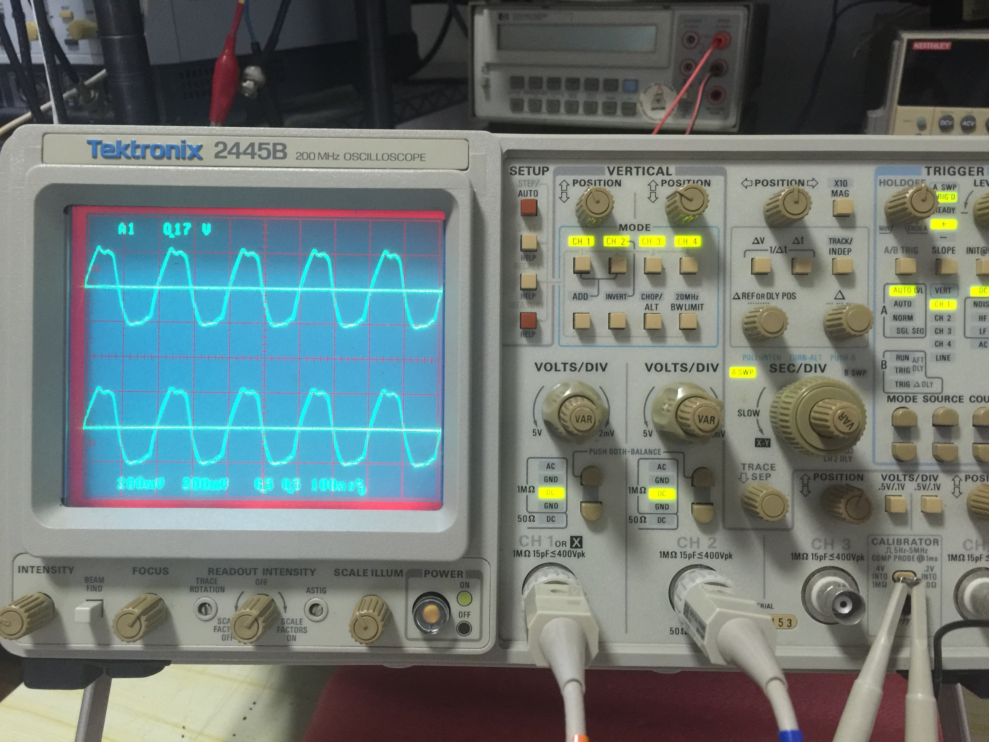
This scope failed 3 years ago and the symptom was just no display after power on but some LEDs flicks to a point and stopped at “ADD” LED there!  Recently I take it out and attempt to repair it.

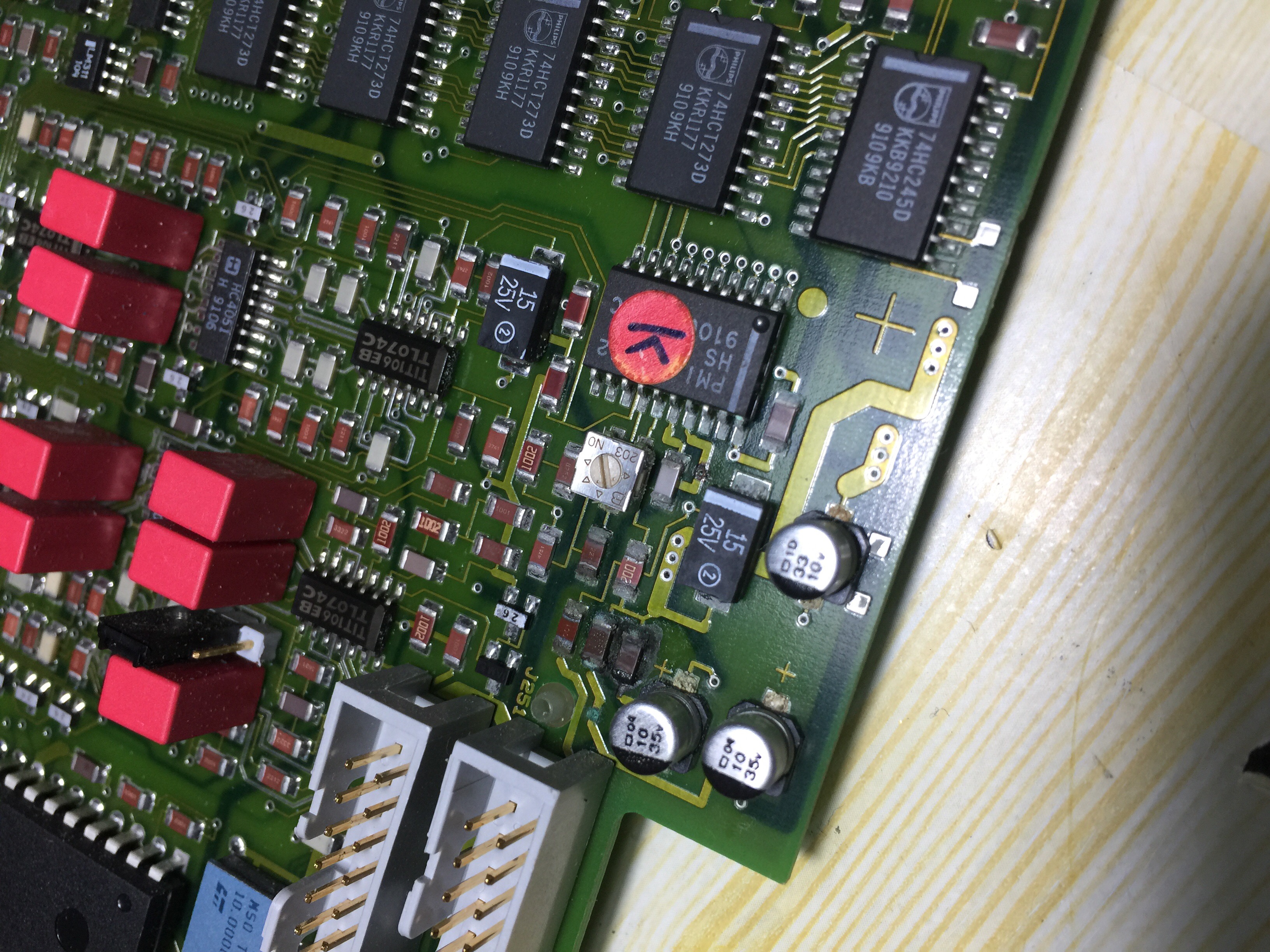
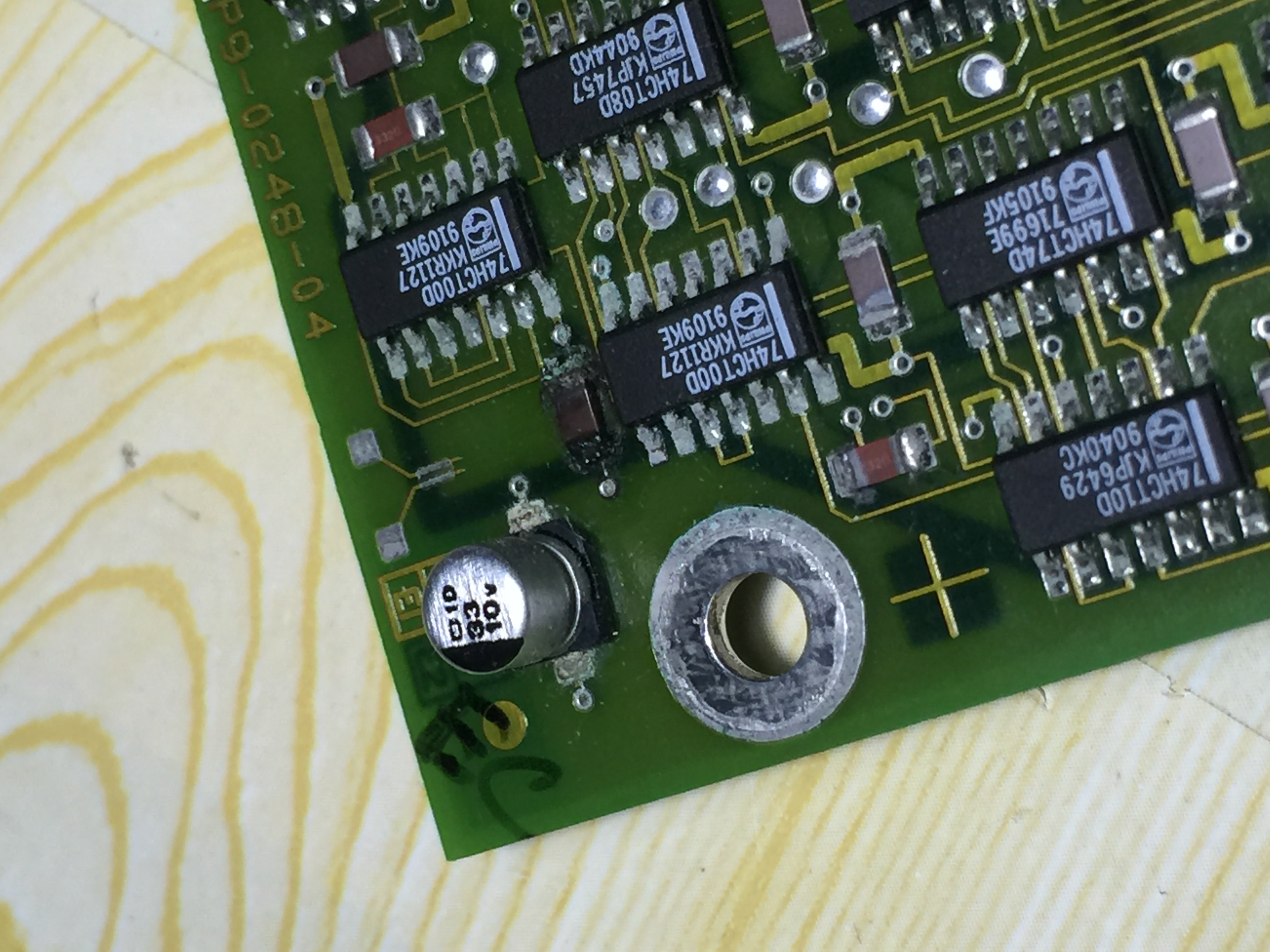
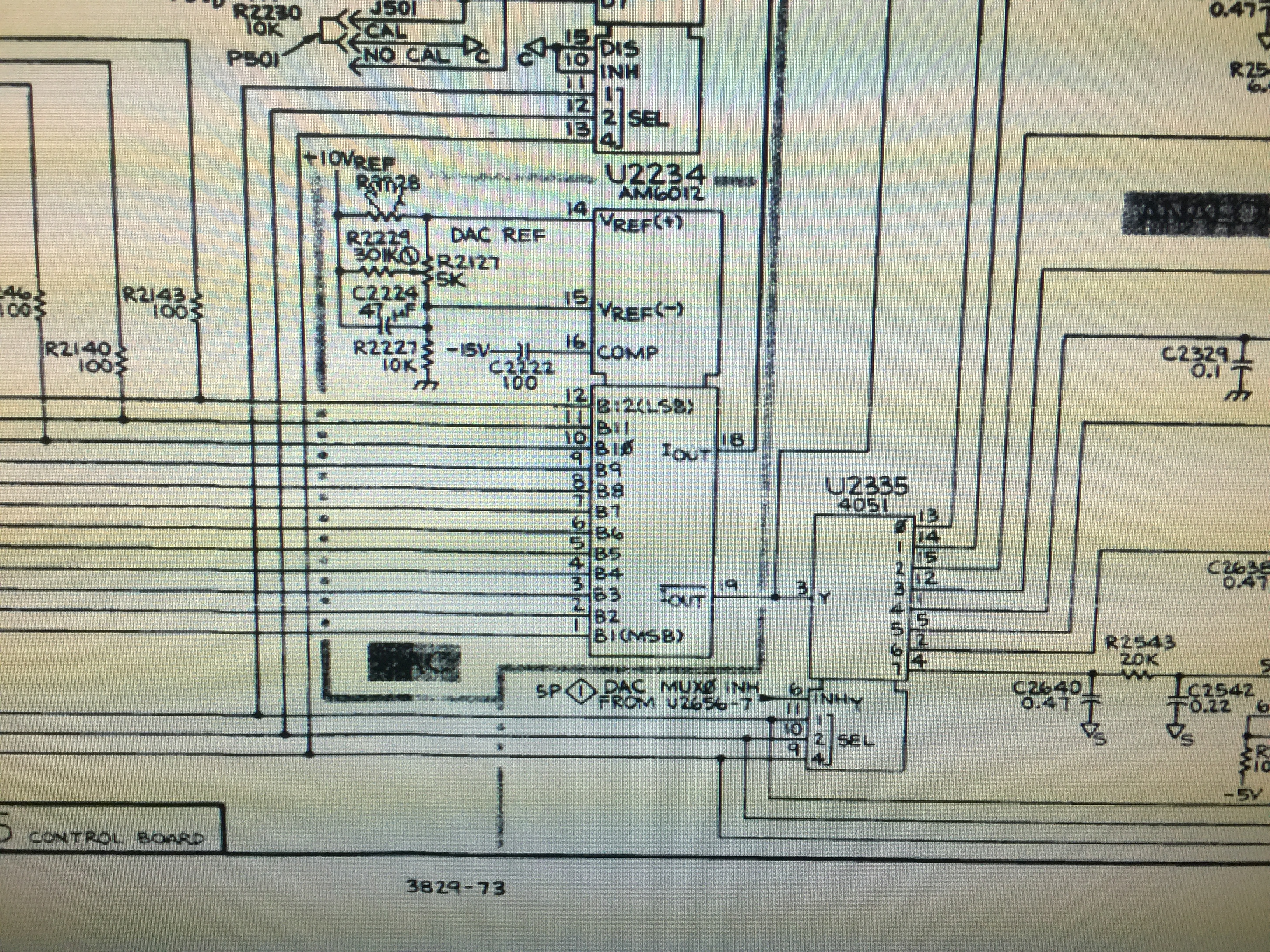
The first suspect is the high voltage board defective and I open it and do a check on the high voltage board switching transistor and everything looks fine.  Also I can get about 65k switching frequency at the switch mode power supply.  After looking around, I see there is a “G Bias” pot on the high voltage board and then I turn it clockwise and see some display DOT on the screen.  The scope wordings of time base and input attention can be seen also.  Thus I reboot it and see a “Step 05 fail 44” error on the screen.  After checking the service manual it point to the DAC on the control board and thus I look at it again.  Oh I find the leaking SMD capacitors with corrosion in its surrounding components.

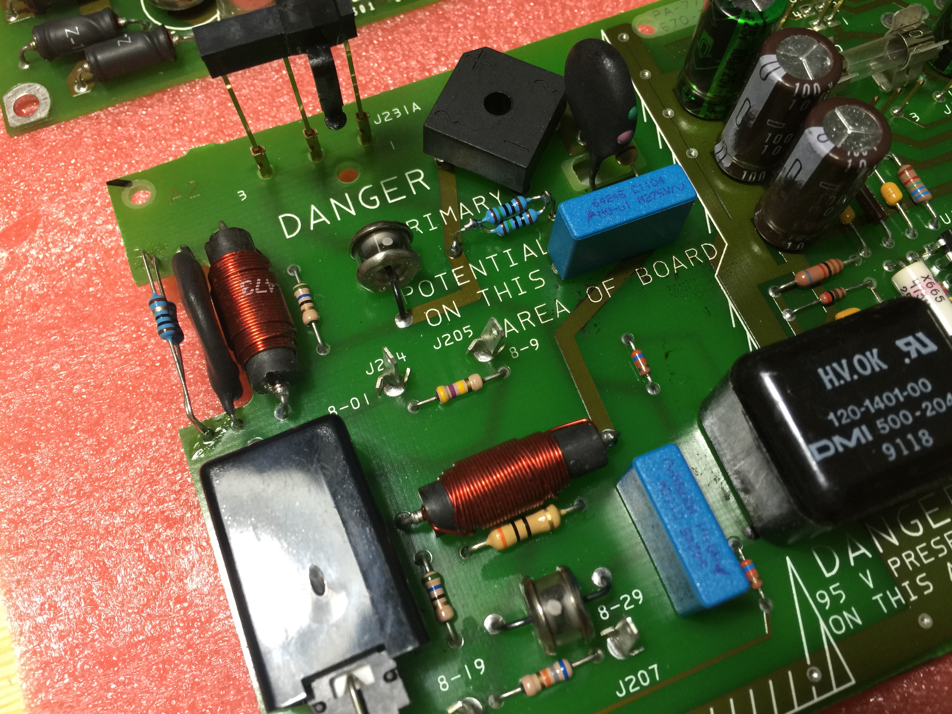
It can be seen that the components surrounding the three E-cap are with corrosion solder join!  So in totally changed all 4 SMD e-caps on the control board as the other corner also have one more leakage e-cap.

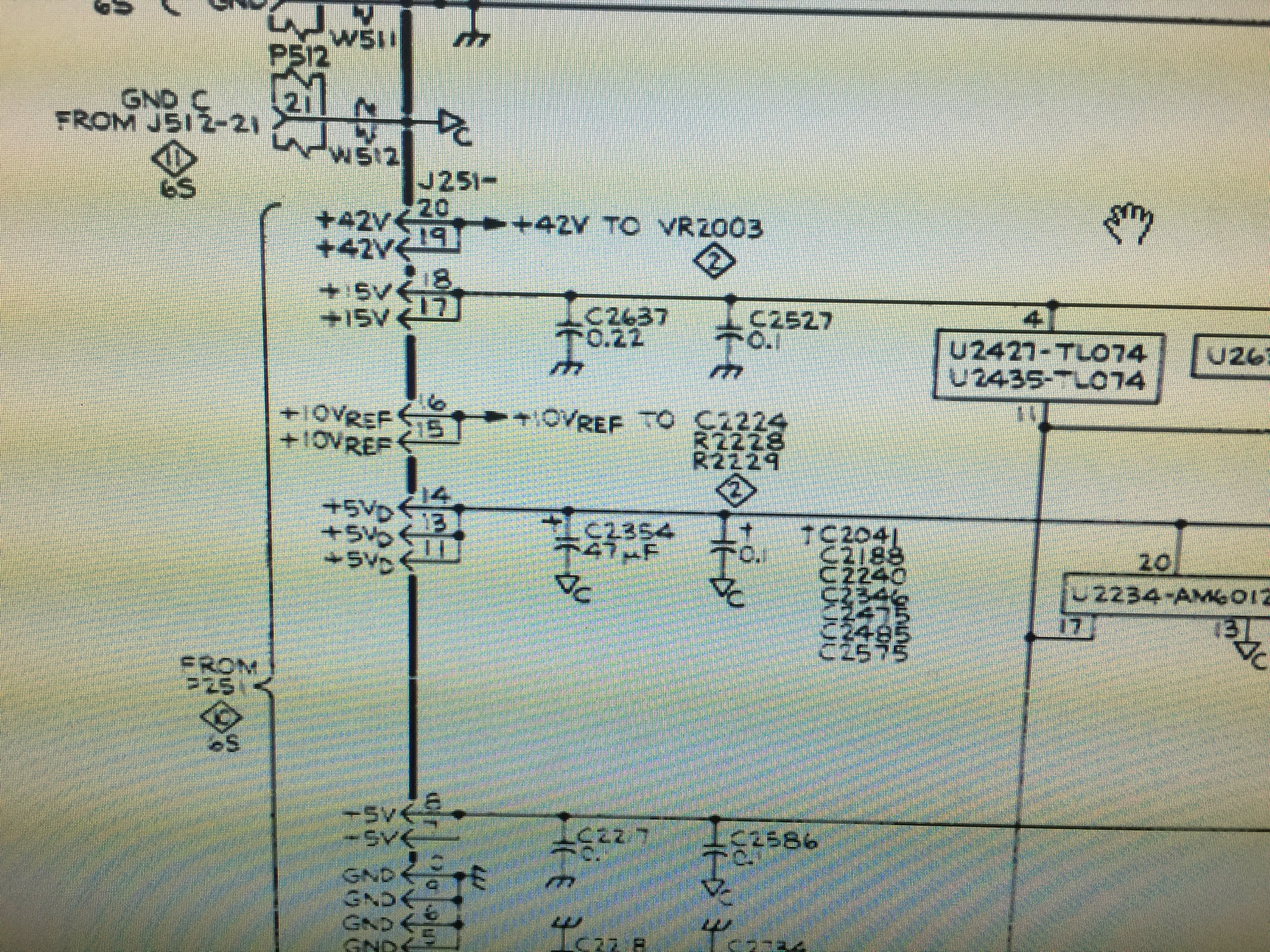
After changed the 4 caps, I put back the board and power on the set but the failure symptom is still same step 05 fail 44!!!  So I probe around the DAC chip and check the Vref 10V at pins 14 and pin 15.  The voltage is really low and close to 0 volt.

So I started to check the components around the DAC U2234 and later find out that the resistor R2228 10k is open circuit.  I replace it with another one smd resistor and after that I power up the set and it works again!

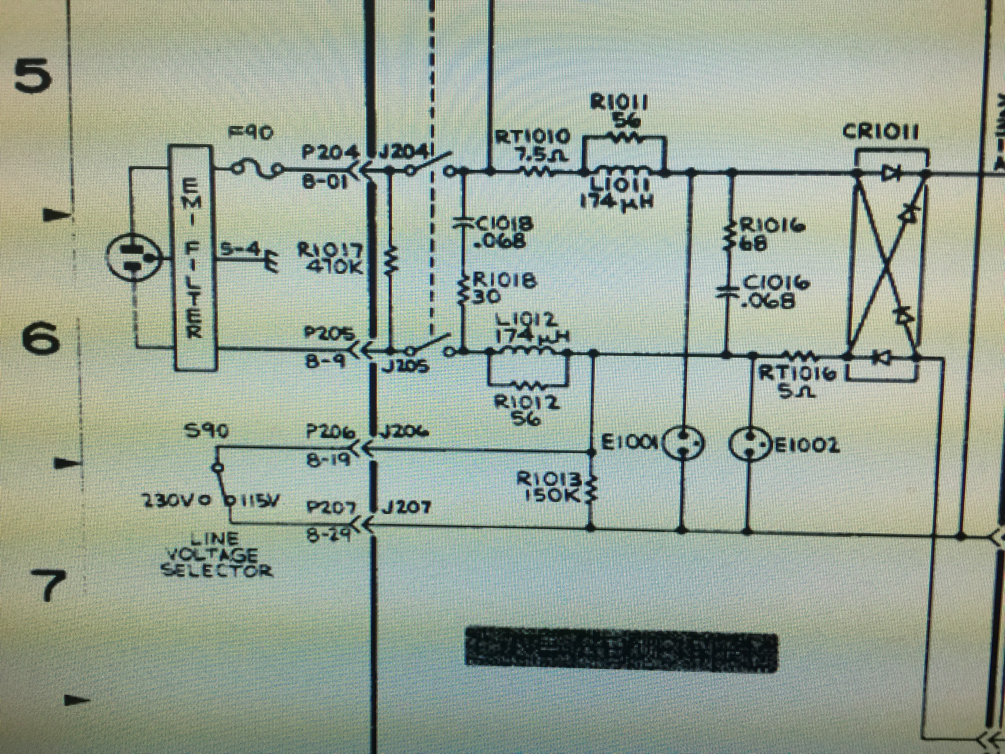
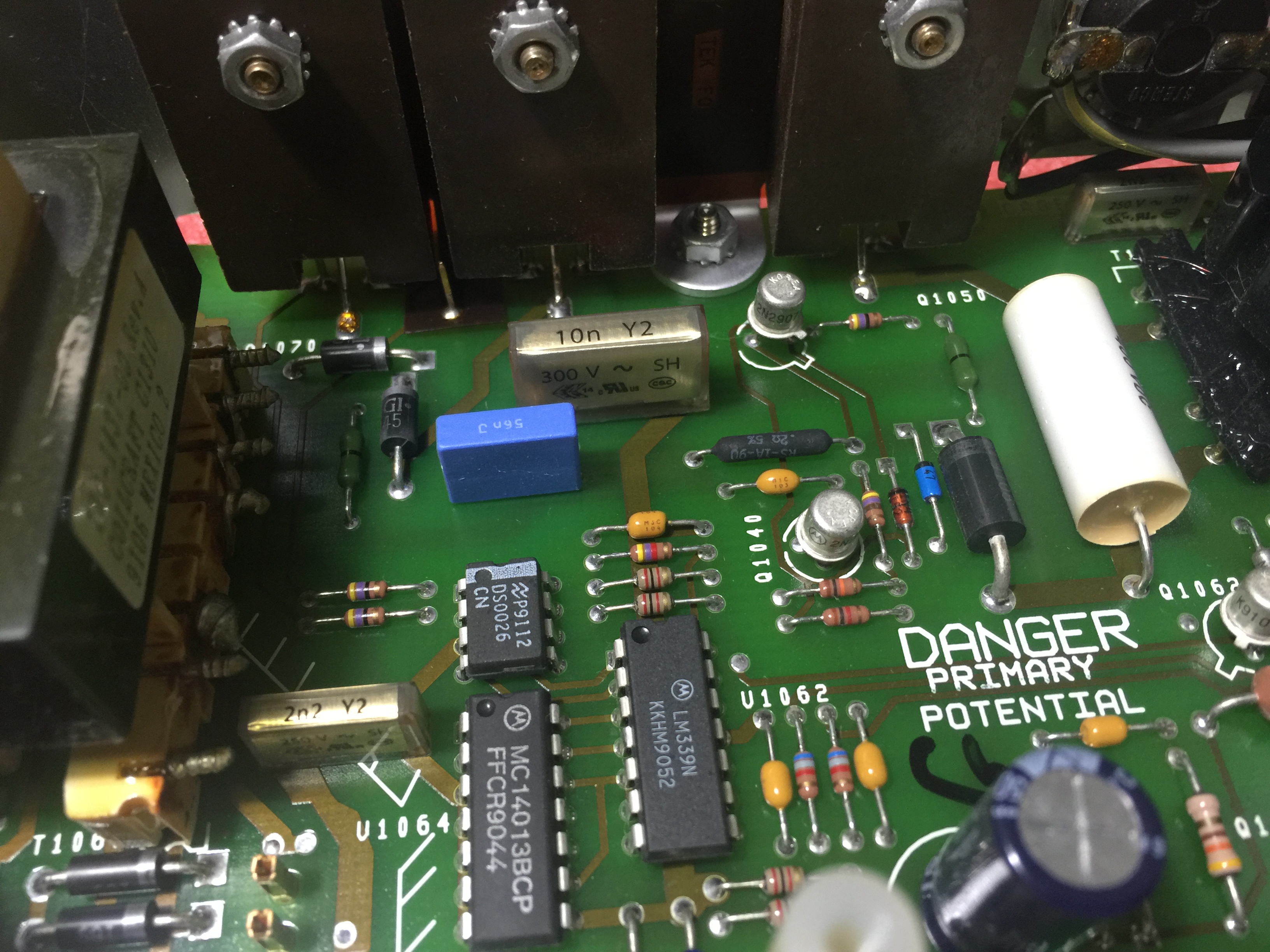
I burn in the set for about 15 mins and then I start to smell something from the scope and of course power off it immediately.  Open up and found the line filter caps (RIFA) brands are all burnt together with two more resistors.

C1018, R1018, C1016, R1010 (parallel with RT1010; 15 ohm not on schematic) were all burnt of open circuits.  Later I also find three more Rifa capacitors on the other PCB (2200pf and 10nF 250v ~ is also crack a bit on the body.  I take them out and all the 2200 pf caps are with very low value of about 100pf!  Thus I order them from element14 and they arrive after 3 days.  For the 0.068u 250V~ cap, I use on hand 0.1uf 250V~ cap to replace them (blue color on the picture).  After put back, everything  works fine.  I have brought this 25 years old scope back to life!

I also note that there are many same scope 2445 or 2445B with similar failure of step 05 fail 44.  I hope this information can help some of the people to repair their scope.

IMG_1128 IMG_1142 IMG_1193 IMG_1195 IMG_1202 IMG_1221IMG_1247 IMG_1251 2445B repair


Related Images:

May 11, 2014

F5T Pre-amp + FDA-2A AD1955 DAC in one box

Filed under: DAC,Pass Amplifiers — Spencer @ 12:52 pm

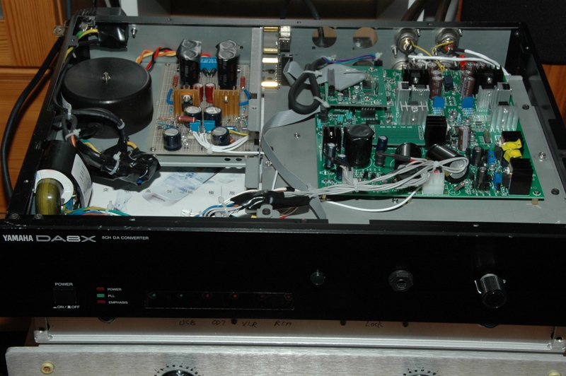
This is a pre-amp plus a FDA-2A in one box.  It was built in year 2012.  I use a old Yamaha DA8X box to house eveythings insides.  See the pdf files at bottom for details.

DAC:

FDA-2A with USB, Optical and AES digital input.  Push button for digital input selection at the front panel.

DAC direct output is available in RCA sockets.

F5T Pre-amp:

Alps volume control from DAC output and note that there is no other analogy input for the preamp.

The pre-amp is based on Nelson Pass F5T power amp design and striped down to only one pair mosfet and lower bias current at about 200mA.  Supplier voltage is at about +/-23V with a small transformer.  Power mosfet is using Toshiba J200 / K1529 pair and casing is acted as the heatsink of power mosfet.

A headphone jack is connected in parallel with the pre-amp RCA sockets.  It can drive most headphones due to sufficient high bias of the power mosfets.

DSC_0045s

Details refer to this pdf file: F5T-Pre_DAC

Enjoy!


Related Images:

November 23, 2012

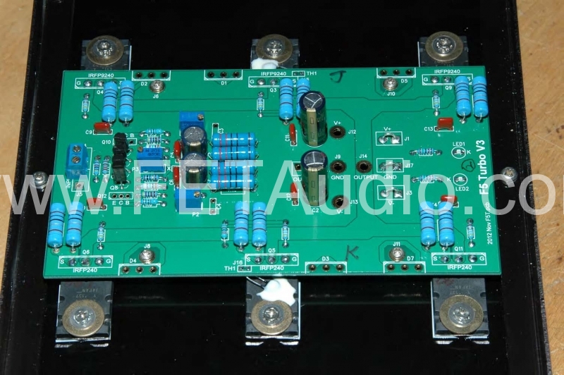
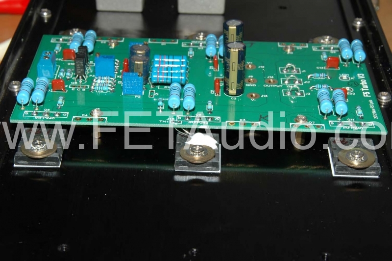
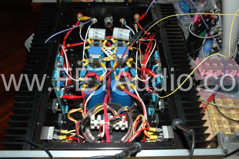
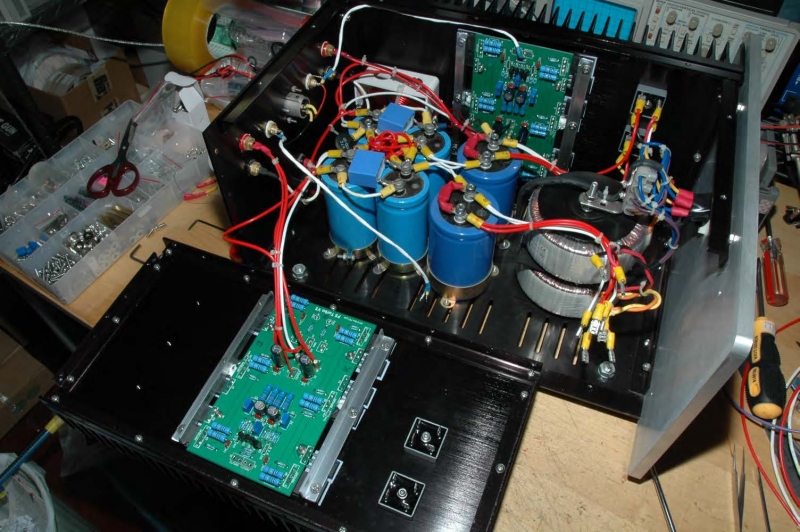
F5T Turbo Power Amplifier kit for sales

Filed under: Pass Amplifiers — Spencer @ 11:01 pm

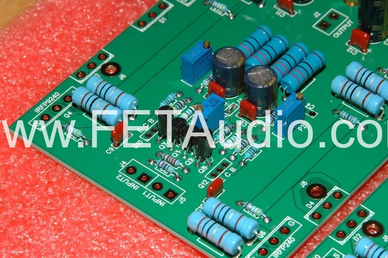
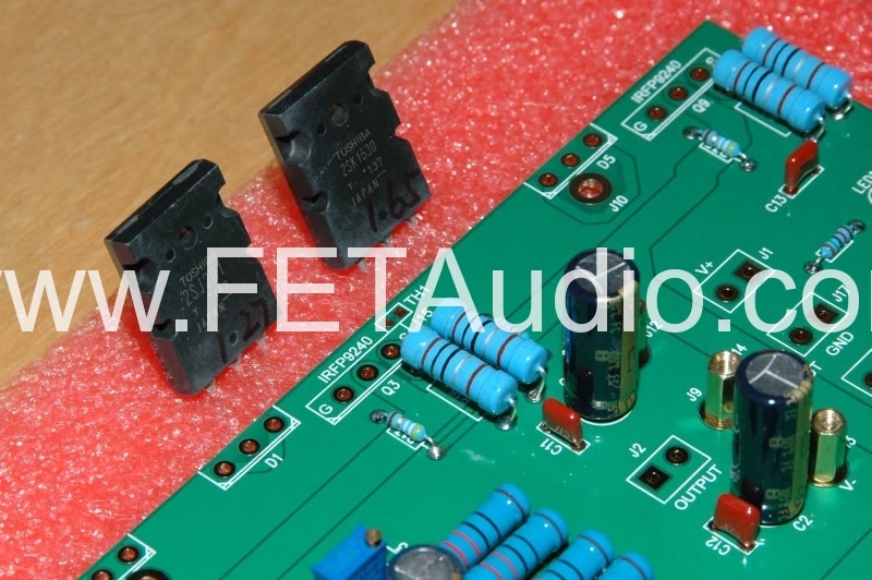
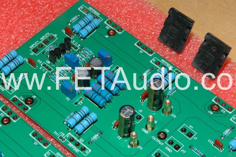
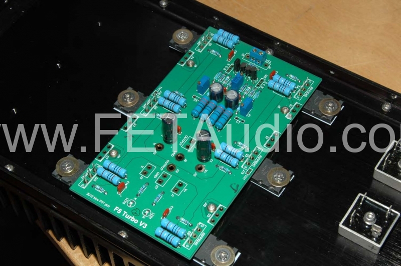
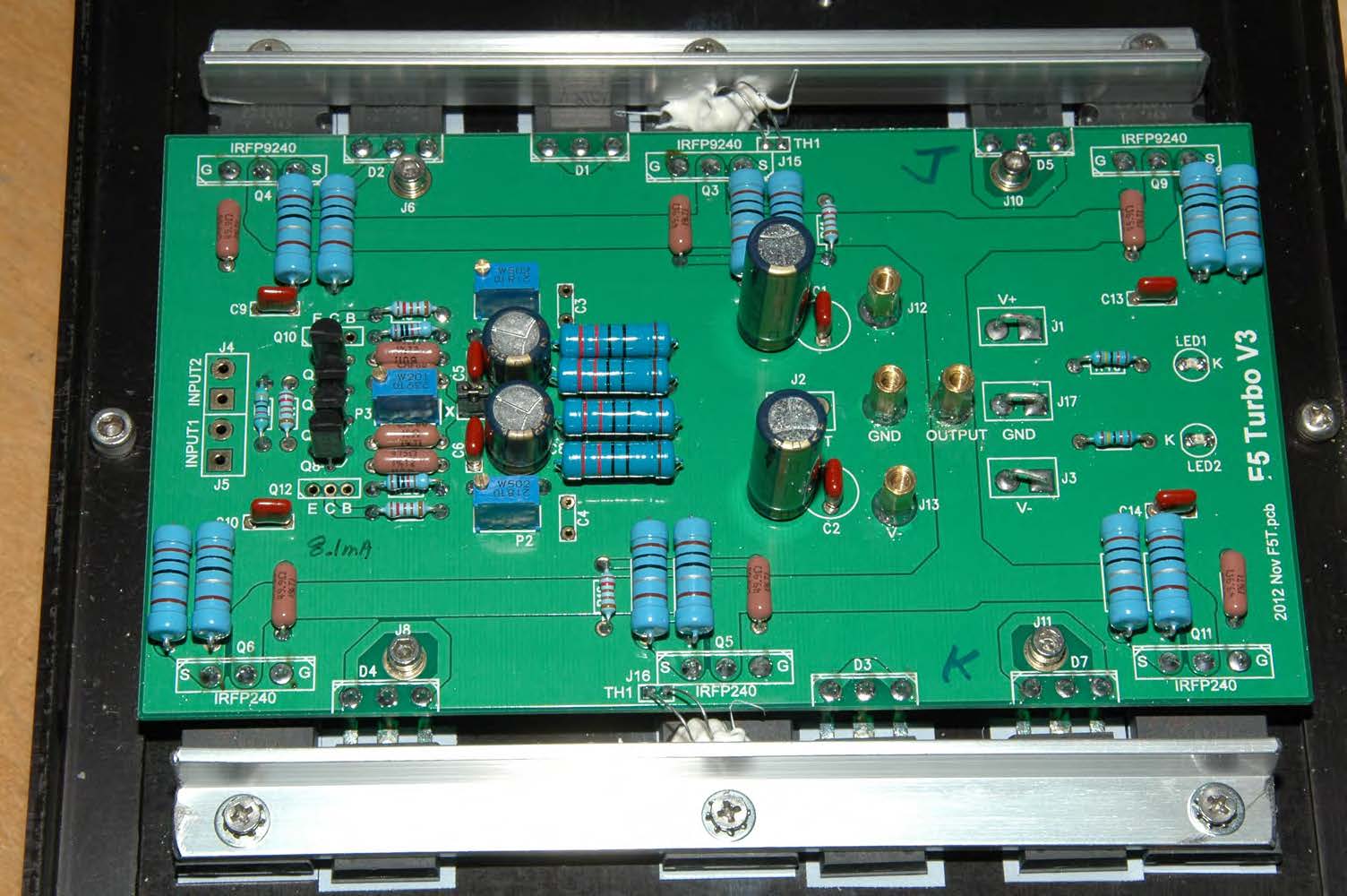
Those who had brought my F4 kits few years ago can purchase this kit or boards for a quick conversion from F4 into F5T because all the holes and mosfet locations will be same as the F4 pcb.  The optional MUR3020W can be obmitted if not use.   If F4 buyer has the original IRF9240/240 power mosfet, it can be re-used.

The To-92D transistor are Toshiba 2SC2705Y/2SA1145Y rated at 800mW and thus it is very safe to use at 60 deg C environment for less than 200mW dissipation.  It would survive safely under a maximum supply voltage of +/-32V.  The Panasonic capacitor is rated at 35V and thus a supply voltage of no more than +/-32V is recommended for this kit.

I build a version using Toshiba Mosfet 2SK1530/2SJ201.  The supply voltage is +/-22V and thus I do not use the cascade transistors (2SC2705Y and 2SA1145Y).  I also change 3 resistors and details refer to the “F5T-BOM-cost” document.  The change on R11/R12 is to increase the thermal stability and R27/R28 is for increasing the supply voltage to jfets to be minimum 10V or above for a supply voltage of 22V.  49.9R to replace 47R do to stock issue.

Sound wise, it is more powerful than the F5 original due to higher current output and more pairs of mosfet is used.  Overall the sound is smoother and warmer than F5. Nelson said this amp sound more relax!

Please look at the F5T-BOM-cost documents for the detail kits offer – Price & BOM options.

Details: F5T-BOM-Cost_2017 (updated transistors prices)

Manual: F5 Turbo Assembly Instruction v3

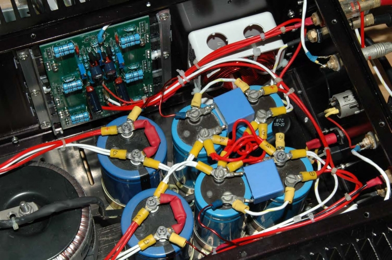
Power supply ripple comparison CLC vs CRC: It can be seen that an inductor of 0.47mH air-coil has improved the ripple peak to peak level to 20 times smaller.  See attached: F5T ripple

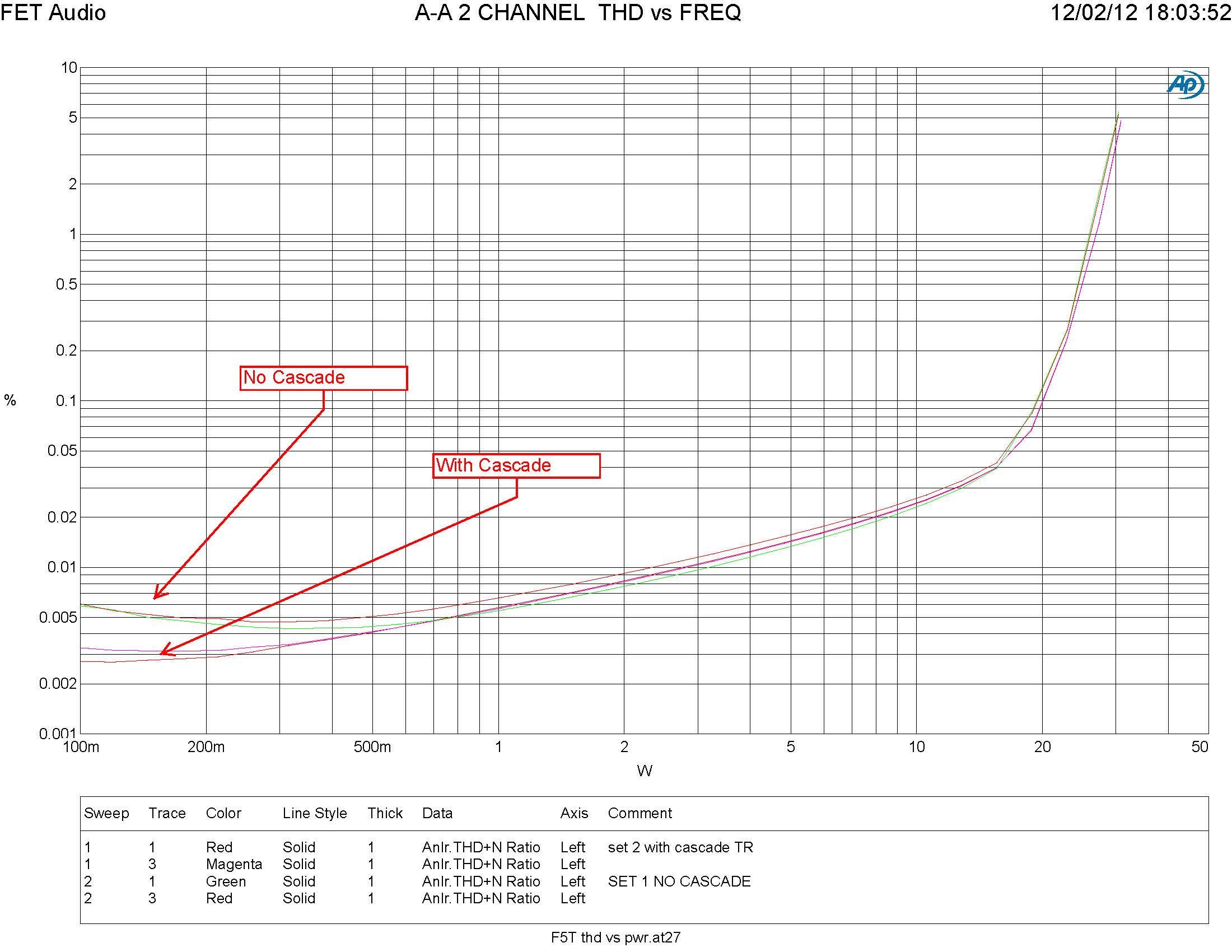
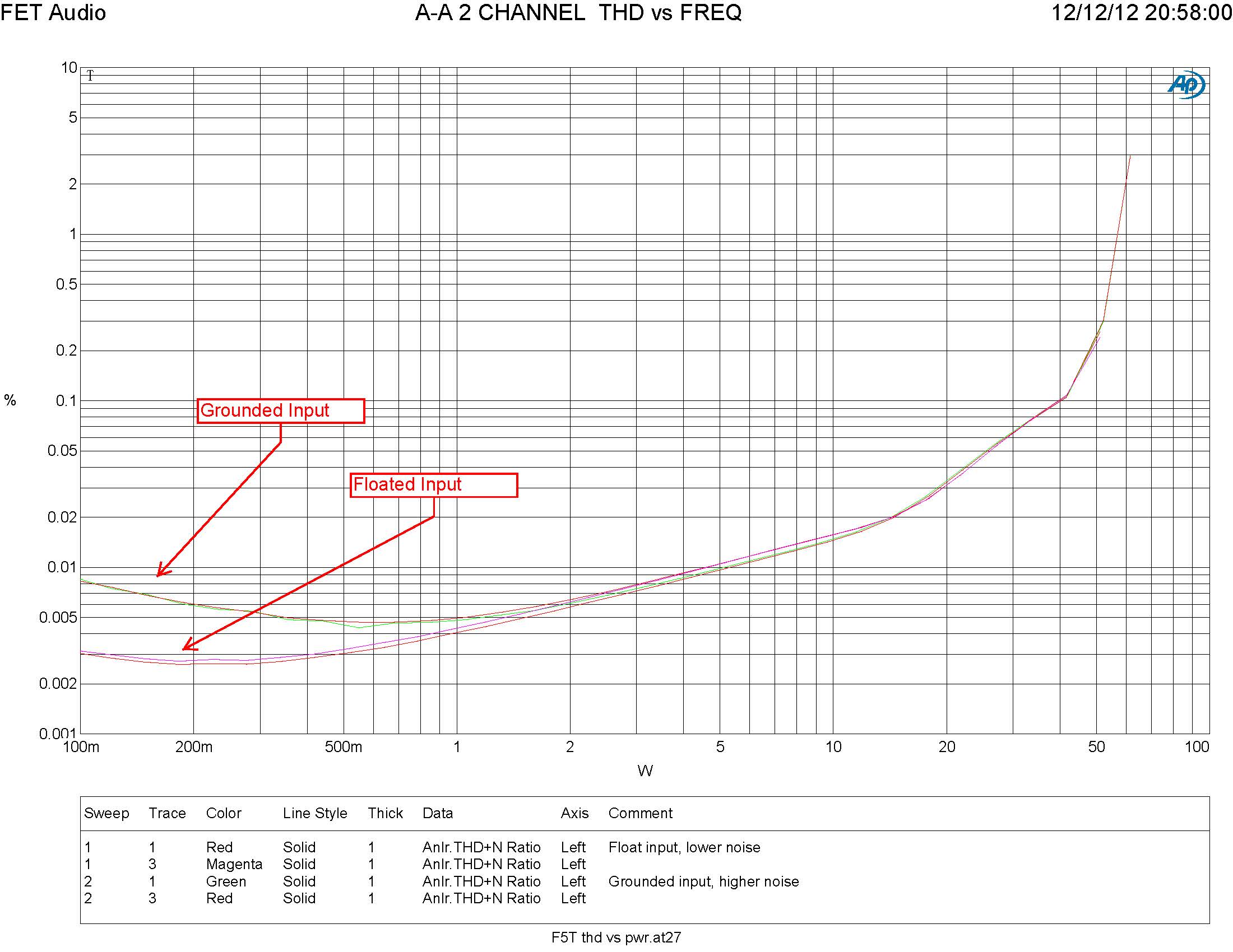
After building another set with Cascade transistors, the noise level with grounded input is about half of that without cascade transistors.  The reason is that the filtering of the transistors at the base is much better and thus the jfets is supplied with a more stable supply with lower noise level.  Here is the measurement comparison.

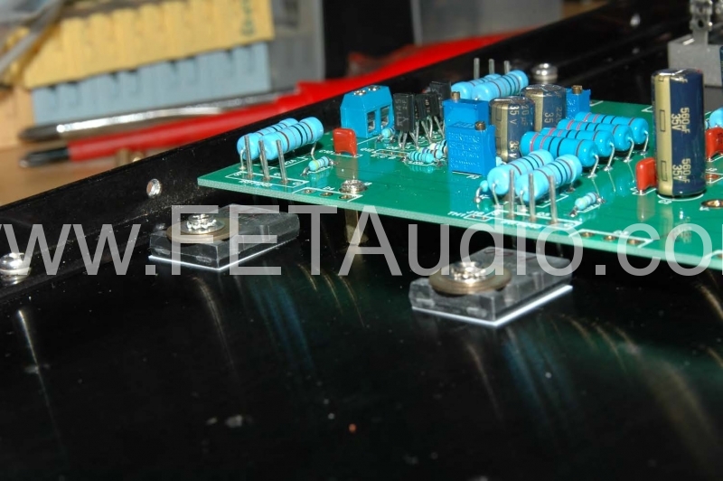
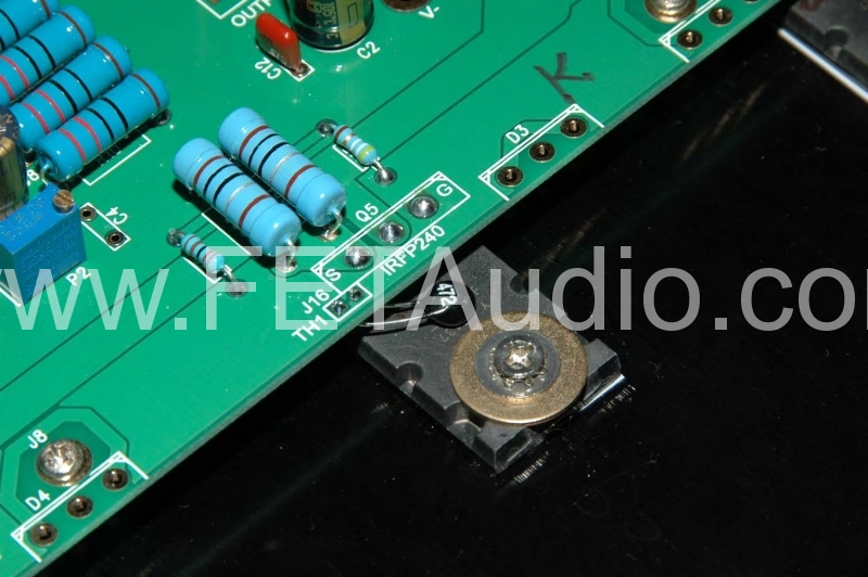
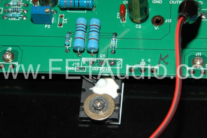
Notes for F4 up-graders:  For the MUR3020W, I have no pre-tap holes for them and thus I use a L-Bar to fix the 3 power mosfet and MUR3020W as shown.

I have built the third set with 32V supply as suggested by Nelson Pass.  Here is the measurement of distortion vs Power Output at 8.2 ohm load.  With higher supply voltage, the distortion is lower at 0.004% 1W.  The non-cliped output is about 50W.  For this measurement, the bias is about 1.6A to 1.7A  for each channel.  The conclusion is that the distortion is lower at 32V and higher at 22V supply.  With no surprise, this set sound the best after adding the Solen 1mH coil in  the power supply (CLC) filter.

Related Images:

« Newer PostsOlder Posts »

Powered by WordPress