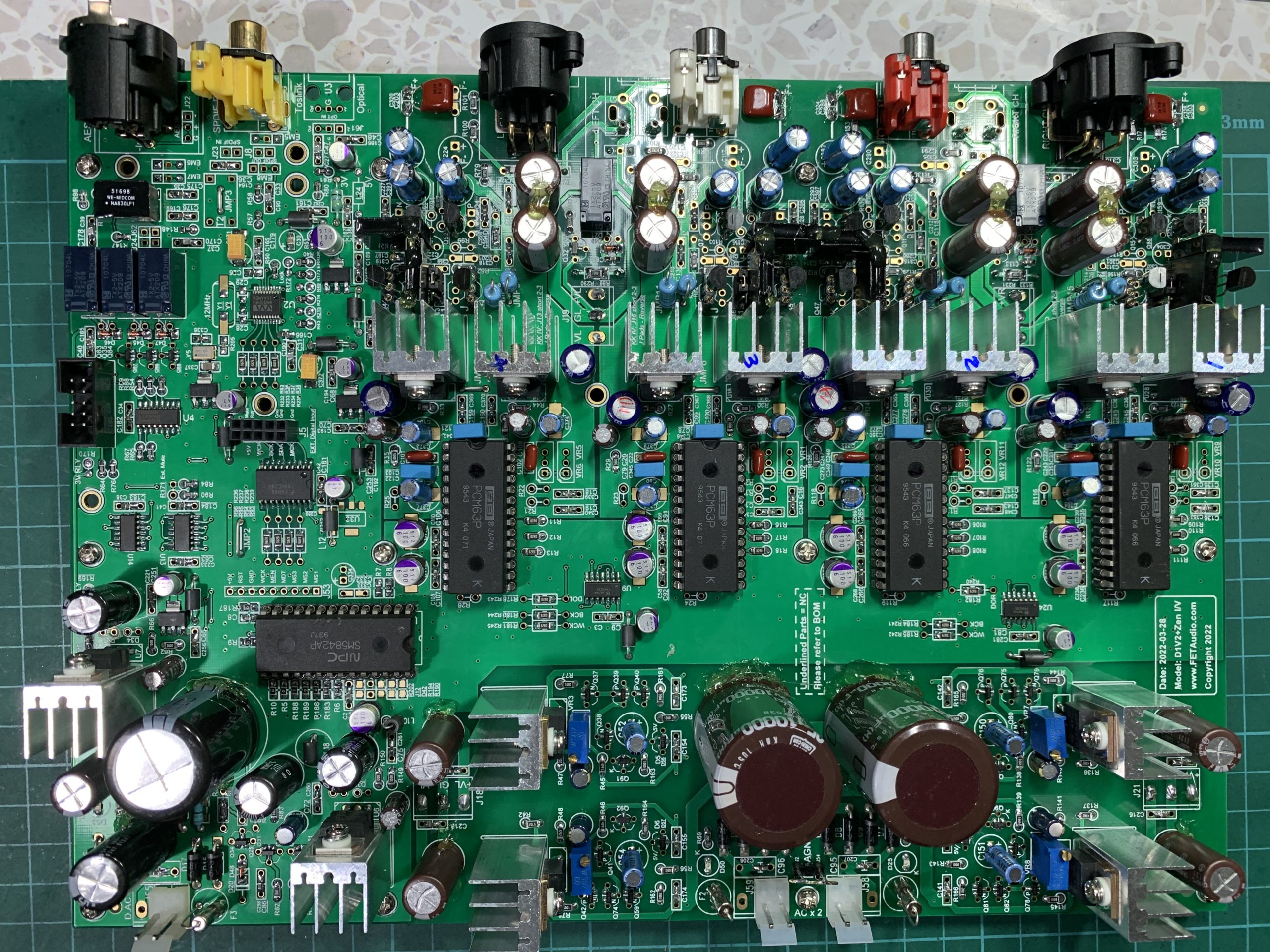
PCM1794A DAC V2 / PCM1794 for Sale
August 25, 2010 - filed under: DAC,Shop
A. Introduction:
This kit is designed to replace the obsolete PCM63 balance DAC kit (aka D1V3 and D1V33). This PCM1794A DAC V2 will provide the same sonic performance level of D1 but with better resolution and dynamics for today’s 24bit/192k high resolution recording.
This DAC is designed for the serious audiophile. It utilizes the best DAC chip available that is capable of producing a super dynamic range of 127db! It also utilizes many custom circuit designs and discrete components that result in a very low THD and an ultra low noise floor!
Rather than using the standard OP Amp, the IV Section is custom designed and uses discrete transistors that feed a pure ‘Class A’ no negative feedback driver and output buffer stage.
This ‘serious audiophile’ DAC is peppered with high quality audiophile grade components that are selected because of their complementary sonic signatures after many exhaustive hours of listening tests.
However, the most important feature is that this DAC sounds musical, dynamic, open and warm with an unparalleled resolving power. It is truly a remarkable DAC capable of holding itself against any branded DAC costing many times more!
.
B. Specifications:
- DAC: Texas Instruments PCM1794A 24bit/192k best in class DAC chip
- Digital Receiver: Crystal CS8416 24bit/192k digital receiver
- IV and Analogy Filter: Discrete transistor IV (current steering) operating in pure Class A mode with NO feedback for the best sonic performance
- Digital Input: SPDIF, AES, Toslink and I2S Bus (RCA, XLR female, Optical and 8×2-pin header)
- Bit/Sampling Frequency: Up to 24bit/192k
- Analogy Output: Stereo Channels (Single End) @ 1.5Vrms (expandable to Balanced output by using two boards @ 3Vrms)
- Auto muting for noiseless operation when no audio/digital signal is detected or when a digital error occurs (e.g. AC-3 signal) or when powering up or down
- Power supply: AC 17~18V x 2, 0.5A and AC 8~9V x 1, 0.5A
- Display LEDs: PLL Lock, 48k, 96k and Mute (for 8416 input only)
- Distortion: Typically at or less than 0.02% 1kHz at FS, 20kBW Single Ended @ 1.5Vrms. At full bandwidth typically no more than 0.04%.
- Board: 6 x 8 inches double sided 1.6mm gold plated FR4; 6 x M3 supporting holes; max height part 35mm.
C. Component choices:
A lot of Audio grade components are included in the kit:
- Elna silmic II capacitors in all analogy power supply
- Russian PIO K40Y-9 for Low Pass Filter in IV section
- Sanyo OS-Con capacitors in digital supply
- Panasonic film capacitors for supply bypass
- Vishay Dale resistors in all signal path
- Low ESR filter capacitors by NCC or Panasonic
- High speed rectifiers BYV27 series
Refer to Bill of Materials for component provided in the kit.
-
D. These are new pictures:
.
Please click on the link below to download complete manual for Product Specifications, Circuit Description, Circuit Diagrams, Assembly Instructions, PCB Layout, Interface Specifications, Bill of Materials and FFT measurements:
PCM1794A DAC BOM for Single Ended kit and Balance upgrade kit (new)
Obsoleted Document:
Price information refer to Store page: http://www.fetaudio.com/store
Comments Off
D1V33 from Olivier – France
August 25, 2010 - filed under: Gallery
This is some picture and description of the D1V33 kit from Olivier – France to share with DIYers.
- concerning the 24 bits mod. Here find a link to a photo i did. Instead to cut the PCB, solder a wire, i removed the P10 pin and soldered a wire from P10 to the jumper “GND”. Easier for me… http://www.homecinema-fr.com/forum/download/file.php?id=91284&mode=view
- i put a trigger in my casing. In this way, the DAC switch on automatically when my DIY preamp is on. I like it !
- i connected the GND of your DAC to the earth of the IEC through a 10R (in mine 18R because i was stock out….) 3W resistor. I don’t have any “humm” or any noise with this way
- an finally i put your name on my backplate.
Comments Off
PCM1794A DAC – Version 1, PCM1794
June 27, 2010 - filed under: DAC
The DAC is base on the circuit of the hardwire version with some additional features.
- Digital Input: I2S (via pin header), SPDIF – RCA, AES and Toslink (optical); selected by two pins 00/01/10/11 for all 4 inputs. Default input is RCA – SPDIF without selector sub-pcb.
- Output: RCA Left and Right (about 1.5Vrms); mute by relay shorting output signal to ground
- Display: 3 LED - Mute, 48k, 96k; Fs display is for 8416 only!
- For Analogy Balance output, two pcb are required and one pcb jumpers will be set to Mono L and the other set to Mono R channel. I2S flat cable is reqired to connect the source pcb to the slave pcb. To be tested!
- Power input: 18V x 2 0.5A and 9V x 1 0.5A AC
This is the first version and thus there are few minor errors on the pcb: Optical input reversed pin 1 and 3 connection, no mounting holes for optical receiver, no mounting holes for XLR female socket, and non-optimized ground path. Thus some cut trace and jumper wires are reqired on the bottom of the pcb. But anyway the FFT measurement is quite satisfactory after error corrections. Here are the photos and FFT measurements.
From the FFT, you can see the noise floor is about -135dBV (-138dbr). It is about 5dB better than the hardwire version.
1794 DAC V1 FreqResponse & Distortion
Distortion and frequency is about same for both hardwire and Pcb version 1.
Update: June 30, 2010
One pcb is install in the casing and use a better transformer. The FFT is ploted again and 50Hz hum is not seen anymore.
D-A FFT DAC 1794 V1 log (Case set1)