This converter board is to replace CS8412 in my DAC project D1. This is designed to be used in the D1V2, D1V3 and D1V33 versions. There are other DIYer who is interested to use this to replace the CS8412 in their DAC. I have tested that it can be used to drive SM5842, SM5847, PMD100 and TDA1541 etc… Take note that even through it is working fine but the output logic for DIR9001 is only 3.3V while all the old ICs are at 5V logic. ACT logic should be used if 3.3V logic is needed to buffer up to 5V.
Another important note is the EMPH (pin 3) output in DIR9001 Converter BD is High when the data has pre-emphasis data added. In a CS8412 or CS8414 chip, the pin 3 is LOW when the data has pre-emphasis data added.
The major improvement in DIR9001 is the lower jitter of 50ps (200ps for CS8412/14). The improvement is very obvious in sonic performance of any DAC.
Sorry all sold out!
DIR9001 converter board Manual
DIR9001 converter bd BOM
9001 to 8412 V3 Circuit Diagram

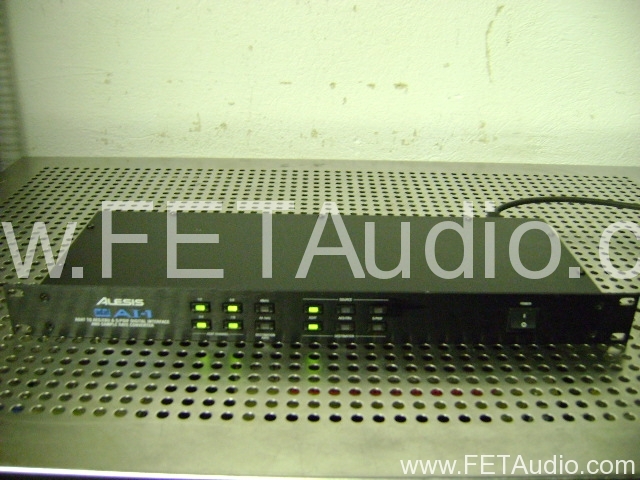
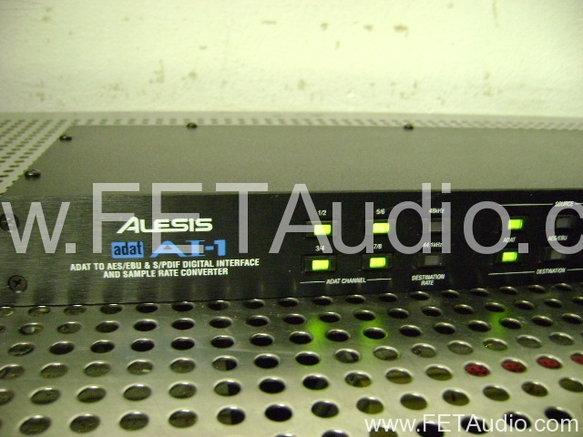
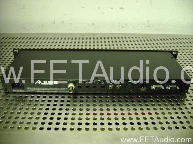
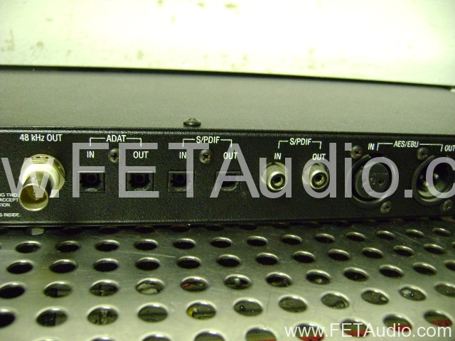
Related Images: